

Introduction: Build a Low Cost, Scrolling LED Display for Your Arduino Microprocessor.


The Arduino Microcomputer system is an affordable platform to learn about microprocessing and programming. Yet Arduinos can be used for instrumentation, robotics and many automated processes.
In this series we will go through some of the basics of software and hardware interfacing and I will show you how to build this simple but effective LED matrix display system.
All you need for the LED display is 30 LEDs of any color, 6 x 390-ohm resistors, 5 x 1N4148 (or 1N914) low power diodes, some thin wires and a small piece of perfboard to hold everything. Total cost, maybe $5.00.
Step 1: Arduino?
Oh yes, you DO need an Arduino processor, which can cost from $30 to $50. Look up http://arduino.cc , BoArduino and Freeduino and pick the one that appeals to you. Software-wise, they are all compatible and virtually interchangeable.
One major consideration is the 'input interface': the means to feed programming and data to your micro. If you are just starting out, I strongly suggest one that uses the USB. With it, not only can you talk to your Micro with your regular computer (WIndows, Mac or Linux), it can, within limits, power the micro as well.
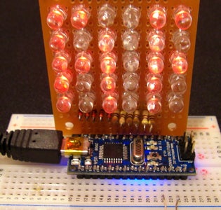
One of the newest member of the Arduino family is the 'Nano', shown here trying to say "HELLO" on the LED panel. It's got everything on a 2" x 1" (5 x 3 cm) package, and has its own USB connection.
The Arduino is an entire developmental system that can interface to the real world: lights, sound, motion and can be connected to sensors that can 'feel' them.
Best of all, the Arduino Foundation is 'open' - all its software is free, and you are encouraged to share and develop your own.
Step 2: The LED Matrix Panel, or LMP

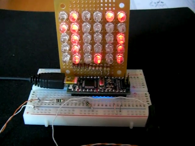
The LMP is 6-columns across by 5-rows down, totalling 30 LEDs. The size is chosen because this size Matrix is the smallest that can be used to display the English alphabet, and wide enough to be used for scrolling messages. It is also the largest matrix that can be built using ONLY the available output pins on 1 side of the Arduino package.
Technically: the columns are controlled by digital pins 2 through 7 (PORTD), while the rows use pins 8 through 12. This form of matrix addressing means that only ONE LED can be lit at any time, but allows us to control 30 LEDs individually without needing expensive multiplexing and addressing hardware.
Before we get to the actual construction, take a look at this youtube video to see some of the display functions that we can use the panel for.
http://www.youtube.com/watch?v=lCBOTupvXIY
Step 3: Begin Assembly

Although it is possible (and tempting) to use LEDs of different colors, it is recommended you stay with ones with similar voltages: reds, ambers, and greens are in the 2v range, while blue, purple and whites are 3v or more. This avoids the problem with grossly varying brightnesses.
Begin with a 2" x 3" (5cm x 7.5cm) piece of perforated circuit board (perfboard) and arrange the LEDs as shown. Align the SHORTER (-) leads towards the top of the board, which I had marked with an arrow.
Making sure the LED is flat against the surface of the board, solder the negative lead ONLY. Do that for all 30 LEDs.
Now fold the longer (+) lead of each LED over to touch its neighbor and solder them together. You should have the + leads of 6 LEDs connected this way, all pointing to the right.
Step 4: Installing the Diodes
You will be fashioning pins to be inserted directly into the MPC board. Make VERY sure that you are able to attach them directly into female headers (sockets) labelled D12 to D8 on the microcomputer board. The larger MPC boards have a gap between pins D7 and D8; make the necessary adjustments to your installation!
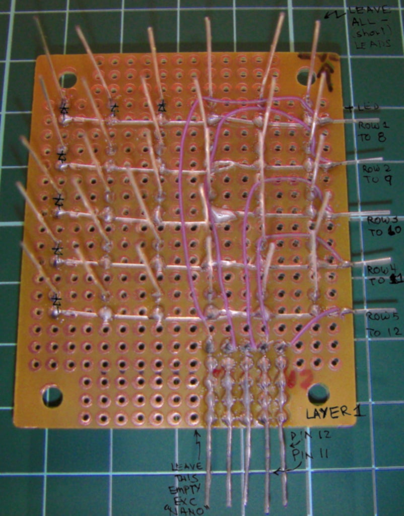
Bend the leads of 5 x 1N4148 diodes to come out the the space at the bottom, with the cathode (-), banded side pointing towards the LEDs. The anode (+) end will attach to the micro's pins. If you find the wires too flimsy as a connector, reinforce them with a heavier wire.
Attach the cathode ends by thin wires to the LED's anode (row) ends: pin 12, row 1; pin 11, row 2; pin 10, row 3; pin 09, row 4 & pin 08, row 5.
Step 5: Add the 2nd Layer + Column Resistors


To isolate the leads of the LEDs, cut a smaller piece of perboard to go over the connections you have already made. Do not make it any bigger than necessary.
Again, match up the pin connectors of the microprocessor with your matrix. Some microcomputer boards have an extra space between pins 7 and 8 and you must allow for that.
Join all the negative (cathode) leads of the LEDs vertically as shown below. Install the 6 resistors to match up with pin 2 (at the end) of the microprocessor with column 6. The other connections are pin 3, col 5; pin 4 col 4; pin 5 col 3; pin 6 col 2 and pin 7 col 1.
After you verified all your connections and trimmed off all the ends, your LMP is complete!
A quick test is to connect a 3 to 6volt source (like 3 or 4 AA batteries) and touch the + to a ROW (pins 8-12) and the - to a COLUMN (pins 2-7), ONE and only one LED should light up.
A word on the choice of resistor. The value (390-ohm) selected is for 8mA to go through the LEDs. This may seem low but the efficiency of the driving program make it unnecessary to use higher power. If absolutely needed, the resistor can be as low as 220-ohms.
Now, if everything looks OK, plug in your LMP, making sure (again) that pins 2 - 12 match up with the sockets on the Arduino. Then you can paste the following program in and see your efforts light up!
Continued in Part 2
Step 6: A Test Sketch
- Copyright (c) 2009 qs@quantsuff.com
- Scanning horizontal and vertical pixels
- LED Matrix row:1-5; col:1-6
- Map PORTB == D8:D12 pin[row+7] : +v
- PORTD == D2:D7 pin[8-col] ; Gnd
- Our output: col::D2:D7 -ve (LOW) while row::D8:D13 +ve
int delayTime= 80; // 1mS increments before next LED
// change from 1-100 and see what happens
int delayStep;
int ledPin, col, row ;
void setup() // run once, when the sketch starts
{
for (ledPin=2; ledPin<=12; ledPin++) // Standard setup for LMP
{ pinMode(ledPin, OUTPUT); // sets the digital pin as output
digitalWrite(ledPin,(ledPin<=7)) ; // and sets all OFF
}
}
void loop() // run over and over again
/* Map PORTB == D8:D13
- PORTD == D0:D7
- Our output: col::D7:D2
- (8-col) -ve (LOW)
- while row::D8:D13 +ve
- (row+7) +ve (HIGH)
{
for (row=1; row<=5; row++) { // Vertical: left to right
digitalWrite(row+7,HIGH); // Enable entire ROW
for (col=1; col<=6; col++) { // then one pixel per col
digitalWrite(8-col,LOW); // gets turned on
delay(delayTime); // for a moment
digitalWrite(8-col,HIGH); // then OFF
} // before next one
digitalWrite(row+7, LOW); // We're done with this row
}
for (col=6; col>=1; col--) { // Going UP right to left
digitalWrite(8-col,LOW); // A shortcut: leave col enabled
for (row=5; row>=1; row--) {
digitalWrite(row+7,HIGH); // Turn 1 pixel on
delay(delayTime); // Wait a moment
digitalWrite(row+7,LOW); // then off...
}
digitalWrite(8-col,HIGH); // finished with this column
}
}


