

Introduction: Conductive Thread Pressure Sensor


The resistance range of these pressure sensors depends a lot on the initial pressure. Ideally you have above 2M ohm resistance between both contacts when the sensor is lying flat. But this can vary, depending on how the sensor is sewn and how big the overlap of the adjacent conductive surfaces are. This is why i choose to sew the contacts as diagonal stitches of conductive thread - to minimize the overlap of conductive surface. But only the slightest touch of the finger will generally bring the resistance down to a few Kilo ohm and, when fully pressured, it goes down to about 200 ohm. The sensor still detects a difference, right down to about as hard as you can press with your fingers. The range is non-linear and gets smaller as the resistance decreases.
I am also selling these handmade Thread Pressure Sensors via Etsy. Although it is much cheaper to make your own, purchasing one will help me support my prototyping and development costs >>
http://www.etsy.com/shop.php?user_id=5178109
As in all my Instructables the materials used for the sensor are basically cheap and off-the-shelf. There are other places that sell conductive fabrics and Velostat, but LessEMF is a convenient option for both, especially for shipping within North America. But they also ship to Europe within about 10 days.
Velostat is the brand name for the plastic bags in which sensitive electronic components come packaged in. Also called anti-static, ex-static, carbon infused plastic (So you can also cut up one of these black plastic bags if you have one at hand. But caution! Not all of them work, so test them first!)
To make the sensor fully fabric one can use EeonTex conductive textile (www.eeonyx.com) instead of the plastic Velostat. Eeonyx normally only manufacture and sells its coated fabrics in minimum amounts of 100yds, but 7x10 inch (17.8x25.4 cm) samples are available free of charge and larger samples of 1 to 5 yards for a minimum fee per yard.
Step 1: Materials and Tool

MATERIALS:
- 1.5 mm neoprene from http://www.sedochemicals.de
- Conductive thread from www.sparkfun.com
also see http://cnmat.berkeley.edu/resource/conductive_thread
- Stretch conductive fabric from www.lessemf.com
also see http://cnmat.berkeley.edu/resource/stretch_conductive_fabric
- Fusible interfacing from local fabric store or
also see http://www.shoppellon.com
- Velostat by 3M from http://www.lessemf.com
also see http://cnmat.berkeley.edu/resource/velostat_resistive_plastic
- Regular thread
- Machine poppers/snaps
TOOLS:
- Pen and paper
- Fabric scissors
- Iron
- Sewing needle
- Popper/snap machine (handheld or hammer and simple version)
Step 2: Create Your Stencil


Decide on a shape for your pressure sensor. Consider that you will need to create two separate tabs for the two layers of conductive fabric and that these should not touch each other (see pictures). Sketch the shape for your sensor onto some paper or cardboard, including both tabs. You will also want to plan where to make your conductive thread stitches in the center or the sensitive area of your pressure sensor. One stitch is the minimum and the more stitches the more sensitive your sensor will be, in the sense that you will hit the least resistance with much less pressure. So best to do as few stitches as necessary to evenly cover the area you want to cover.
Step 3: Prepare Your Materials


Trace your stencil onto the neoprene twice and cut both out. And trace the stencil once onto the Velostat, but cut out the shape from the Velostat 2-3 mm smaller than the stencil and don't include the tabs.
Cut two small pieces of conductive fabric the size of your tabs or slightly smaller and iron these on to the neoprene with the fusible.
Mark with a fabric pen or a permanent marker where you will be stitching with the conductive thread. Make sure the markings on each side are identical so that when you lay both sides on top of each other the identical stitches are sure to cross each other in an X like manor and not match up. This way each two stitches will be sure to cross each other and make direct contact in only one point.
Step 4: Sew Your Stitches


Take the conductive thread single and stitch into the neoprene from the back so that the knot stays on the outside of the sensor. Now stitch your stitches but there is no need to go all the way through the neoprene so that they are visible and vulnerable on the outside. You can dive into the neoprene and at the same time this isolates the conductive thread. When you have finished you stitches you will want to bring the thread to the patch of conductive fabric that is fused to the tab. If you plan ahead you can aim to end close by. With about 5 to 7 stitches attach the conductive thread to this patch and then cut it.
Do the same on the other side of neoprene.
Step 5: Sew Things Together


Layer your piece of Velostat between the two pieces of neoprene with the conductive stitches facing inwards. Thread a needle with regular thread and sew around the edges. Do not sew too tight or you will have high initial pressure. If you want to increase the resistance, lower the sensitivity then add one or two or more layers of Velostat in between.
Step 6: Poppers


Read the instructions on how to use your popper machine. Attach a female popper to one tab and a male popper to the other tab, preferable facing the same side. Make sure that the popper goes through the patch of conductive fabric. This way it is connected with the conductive thread stitches.
Step 7: Visualizing

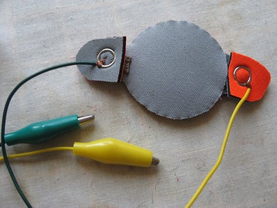
If you happen to be working a lot with poppers and circuits you might like to modify a set of crocodile clips to have poppers on one end. Otherwise you can just clip on to the poppers.
To visualize with a multimeter, create the following setup (see pictures)
Set multimeter to measure resistance (in Ohm).
Multimeter plus to one side of fabric pressure sensor (doesn't matter which side) and multimeter minus to other side of fabric pressure sensor. Apply pressure and watch the resistance value change. You might have to adjust the range if you don't see anything. If you have a constant connection then either you forgot to put the Velostat in between or somewhere your two pieces of conductive thread are touching. Ops.
To visualize with an LED or vibration motor, create the following setup:
Connect the plus of two AA batteries or a 5V source to one side of the pressure sensor (doesn't matter which side) and connect the other side of the pressure sensor to the plus of an LED or either side of the vibration motor (switching plus minus only affects the direction of the vibration motor, whereas an LED only works in one direction). Connect the minus of the LED or the other other side of the vibration motor to the minus of the power supply.
Apply pressure to the fabric pressure sensor and control the brightness of the LED or the strength of the vibration.
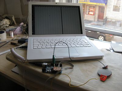
In the video I have hooked up the pressure sensor to an arduino (www.arduino.cc) and am visualizing the change in resistance with a simple application written processing (www.processing.org).
For Arduino microcontroller code and Processing visualization code please look here >> http://www.kobakant.at/DIY/?cat=347
ENJOY!


