

Introduction: Doc Brown's Security Briefcase


I like to think that Back to The Future's Doc Brown would have a security briefcase of his own design, instead of a combination lock, it would only open at 88MPH
I used the Mediatek Linkit One board and an old briefcase to make my own version.
This project is undoubtedly silly, but through it I will describe how to use the Linkit One's GPS to determine speed as well as how to display it on a seven segment display.
The locking mechanism is driven by a servo, also controlled by the Linkit One.
Step 1: Parts Required

- Mediatek LinkIt One
- Servo (I used a Corona DS-239MG Digital Slim Wing Servo)
- Battery (inlcuded with Linkit One)
- GPS antenna (inlcuded with Linkit One)
- A case of some sort
- 2 seven segment displays
- A switch or button
- 2 Shift Registers (74HC595)
- Bits of wire
- Protoboard/Perfboard
Step 2: Power From Battery

One of my favorite parts about the Linkit One is that it is supplied with it's own battery and built-in chargin circuit.
All that is required to use the board in battery mode is to set the switch marked "PWR_SW" to the "BAT" position
When the "PWR_SW" is set to "BAT" the Linkit One will also charge via the USB port (but not via the 5V pins)
Step 3: Get Speed From GPS Data

Before we can do anything with the Linkit One's GPS, we need to attach the antenna to the port marked "GPS" on the back of the board.
GPS reported in the form of comma-separated strings, of which there are a whole lot of different types, each with a focus on a different set of data. All that I was interested in for this project was speed, so I used the "recommended minimum data for gps" or "RMC" string which looks something like this:
$GPRMC,123519,A,4807.038,N,01131.000,E,022.4,084.4,230394,003.1,W*6A
This page has a great description of all the string types, here is an extract of the RMC string, you can see that ground speed is indicated in knots and is the 6th item in the list.
The only other piece of info that I required was the status, which is a single character "A" or "V" that indicates whether a GPS lock has been achieved.
      RMC          Recommended Minimum sentence C
     123519       Fix taken at 12:35:19 UTC
     A            Status A=active or V=Void.
     4807.038,N   Latitude 48 deg 07.038' N
     01131.000,E  Longitude 11 deg 31.000' E
     022.4        Speed over the ground in knots
     084.4        Track angle in degrees True
     230394       Date - 23rd of March 1994
     003.1,W      Magnetic Variation
     *6A          The checksum data, always begins with *
In addition, I found this blog post on parsing the data to be very helpful, it is a nice example of using the Linkit One to parse the GPS RMC string.
Step 4: Driving a Servo


Power Consumption
It is worth noting that you usually cannot drive a servo via a USB port, since they tend to consume more current than USB is allowed to supply (100-500mA depending on the port). Fortunately the LinkIt One has a battery, so it can easily supply the current required for a small servo.
Connections
RC servos have 3 pins, Data, Power and GND
I connected mine as follows
| Servo Pin | LinkIt One Pin |
| PWR | 5V |
| GND | GND |
| DATA | D9 |
If you are in any doubt, there are Instructables all over the show on the topic, or you can head straight to the Arduino example page.
Code
The LinkIt One version of the Arduino IDE includes a piece of demo code to drive an RC servo, which is incredibly simple, I have included it below. It is a good idea to test your servo with this code before trying to get fancy.
#include <Servo.h>
#define ard_log Serial.printf

int i;
Servo myservo;

void setup() {
    Serial.begin(115200);
    myservo.attach(9);
    myservo.write(90);

}

void loop() {
    delay(1000);

    i += 3;
    if (i == 180)
        i = 0;
    myservo.write(i);
    ard_log("write [%d]\n", i);
}
Step 5: Driving the Seven Segment Displays


A seven-segment display is just a collection of seven (or eight if it has a decimal point) LEDS, which can be used to display numbers when the correct LEDS are lit.
There are two challenges to using them which I will discuss my solutions to
- Driving 14 LEDS without using up all of our digital output pins
- Determining Which LEDS to light
Drive all 14 LEDS from 3 pins: Shift Registers
Intro
It would require about 14 digital output pins to drive the two seven-segment displays, which is just not practical, instead we make use of shift registers. The full operation of a shift register is beyond the scope of this Instructable, but here is a link to a good tutorial, in fact I based my code off their "Sample 2.3" code.
The connections from the Linkit one to the first shift register are as follows
latchPin 12 = latch = 12 on ard
shift reg 11 = clock = 11 on ard
shift reg 14 = data = 13 on ard
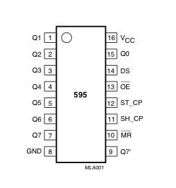 | PINS 1-7, 15 | Q0 " Q7 | Output Pins |
| PIN 8 | GND | Ground, Vss | |
| PIN 9 | Q7" | Serial Out | |
| PIN 10 | MR | Master Reclear, active low | |
| PIN 11 | SH_CP | Shift register clock pin | |
| PIN 12 | ST_CP | Storage register clock pin (latch pin) | |
| PIN 13 | OE | Output enable, active low | |
| PIN 14 | DS | Serial data input | |
| PIN 16 | Vcc | Positive supply voltage |
Make sure that you know whether your displays are common-anode or common-cathode. Mine were common-cathode which meant that I connected each output pin (Q0-Q7) of the shift register to one of the LEDS via a resistor and then connected the common-cathode to ground.
When choosing the resistors for your display, remember that the LinkIt One uses 3.3V IO and not 5.5V like the Arduino. I chose 100 ohm resistors for 17mA current (3.3 - 1.6V = 1.7V across resistor), but should probably have aimed for the full 20mA since they ended up very dull.
Determining Which LEDS to light
I used this table to determine the segments for a given character.
First I made a column for each output pin of the shift register, then a corresponding colum, showing which pin of the 7-segment display it connects to.
Then I used the data sheet of the 7-segment display to correspond it's pin numbers to segments (the segments are labelled a-g)
You can see that I made a column for each character (0-9) and then wrote a 1 if the light must be on and 0 if it must be off (this is actually a truth table). The 'x' are 'dont care' because that pin isn't used.
Reading the column from the bottom up results in a binary number (for example the character 2 gives us X1101101) which we can convert to hex and use in our code (char 2 = 01101101 in binary = 0x6D in hex). I replaced all the X with 0, but it makes no difference.
| Shift Pin | Seg Pin | Seg Name | 0 | 1 | 2 | 3 | 4 | 5 | 6 | 7 | 8 | 9 |
|---|---|---|---|---|---|---|---|---|---|---|---|---|
| Q0 | 2 | A | 1 | 0 | 1 | 1 | 0 | 1 | 1 | 1 | 1 | 1 |
| Q1 | 3 | F | 1 | 0 | 0 | 0 | 1 | 1 | 1 | 0 | 1 | 1 |
| Q2 | 5 | E | 1 | 0 | 1 | 0 | 0 | 0 | 1 | 0 | 1 | 0 |
| Q3 | 9 | D | 1 | 0 | 1 | 1 | 0 | 1 | 1 | 0 | 1 | 0 |
| Q4 | 13 | C | 1 | 1 | 0 | 1 | 1 | 1 | 1 | 1 | 1 | 1 |
| Q5 | 14 | G | 0 | 0 | 1 | 1 | 1 | 1 | 1 | 0 | 1 | 1 |
| Q6 | 15 | B | 1 | 1 | 1 | 1 | 1 | 0 | 0 | 1 | 1 | 1 |
| Q7 | NC | NC | X | X | X | X | X | X | X | X | X | X |
This is the basic code that I used to test that I had the correct bytes for the 10 different characters, it listens on the serial port for a number and outputs it to the first register, there is no error-checking if you input a character that is not 0-9.
/*
  Shift Register Example, modified to drive a seven seg display

 Hardware:
 * 74HC595 shift register
 * LEDs attached to each of the outputs of the shift register

 */
//Pin connected to ST_CP of 74HC595
int latchPin = 12;
//Pin connected to SH_CP of 74HC595
int clockPin = 11;
////Pin connected to DS of 74HC595
int dataPin = 13;

//holders for infromation you're going to pass to shifting function
byte data;
byte dataArray[10];

void setup() {
  //set pins to output because they are addressed in the main loop
  pinMode(latchPin, OUTPUT);
  Serial.begin(9600);

  //Binary notation as comment
  dataArray[0] = 0x5F; //0b01011111
  dataArray[1] = 0x50; //0b01010000
  dataArray[2] = 0x6D; //0b01101101
  dataArray[3] = 0x79; //0b01111001
  dataArray[4] = 0x72; //0b01110010
  dataArray[5] = 0x3B; //0b00111011
  dataArray[6] = 0x3F; //0b00111111
  dataArray[7] = 0x51; //0b01010001
  dataArray[8] = 0x7F; //0b01111111
  dataArray[9] = 0x73; //0b01110011

}

void loop() {
  byte inByte = 0;

  if (Serial.available() > 0) {
    // get incoming byte:
    inByte = Serial.read() - '0';
    inByte = max(inByte, 0);
    inByte = min(inByte, 9);

    //load the light sequence you want from array
    data = dataArray[inByte];
    //ground latchPin and hold low for as long as you are transmitting
    digitalWrite(latchPin, 0);
    //move 'em out
    shiftOut(dataPin, clockPin, data);
    //return the latch pin high to signal chip that it
    //no longer needs to listen for information
    digitalWrite(latchPin, 1);
  }
}


// the heart of the program
void shiftOut(int myDataPin, int myClockPin, byte myDataOut) {
  // This shifts 8 bits out MSB first,
  //on the rising edge of the clock,
  //clock idles low

  //internal function setup
  int i = 0;
  int pinState;
  pinMode(myClockPin, OUTPUT);
  pinMode(myDataPin, OUTPUT);

  //clear everything out just in case to
  //prepare shift register for bit shifting
  digitalWrite(myDataPin, 0);
  digitalWrite(myClockPin, 0);

  //for each bit in the byte myDataOut�
  //NOTICE THAT WE ARE COUNTING DOWN in our for loop
  //This means that %00000001 or "1" will go through such
  //that it will be pin Q0 that lights.
  for (i = 7; i >= 0; i--)  {
    digitalWrite(myClockPin, 0);

    //if the value passed to myDataOut and a bitmask result
    // true then... so if we are at i=6 and our value is
    // %11010100 it would the code compares it to %01000000
    // and proceeds to set pinState to 1.
    if ( myDataOut & (1 << i) ) {
      pinState = 1;
    }
    else {
      pinState = 0;
    }

    //Sets the pin to HIGH or LOW depending on pinState
    digitalWrite(myDataPin, pinState);
    //register shifts bits on upstroke of clock pin
    digitalWrite(myClockPin, 1);
    //zero the data pin after shift to prevent bleed through
    digitalWrite(myDataPin, 0);
  }

  //stop shifting
  digitalWrite(myClockPin, 0);
}

Step 6: Putting It All Together


Connections
Now that we have a speed measurement, a way of displaying it and a locking mechanism, we can turn this into a complete system
Connect up all the peripherals as described in the previous steps:
- Battery
- Displays
- GPS Antenna
- Switch
- Servo
In order to make it easier to connect and disconnect, I attached all the peripherals to a "shield" which is really just a piece of perf-board with 2.54mm (0.1") headers soldered in, as you can see in my photo.
Code
My code is attached, it is simply all the snippets from the previous steps bundled together. I expect it to be updated over the next few days as I do more testing.
Some points are:
- Seven Segment Characters are stored in an array of two-byte hex values called "dataArray"
- getComma() returns the position of the Nth comma in a string
- getDoubleNum(), GetChar() and getIntNum() extract those variables types from a string, between the start of the string and the next comma
- parseGPRMC() uses the previously described functions to extract particular details from an RMC formatted GPS string , in particular, the speed.
- displaySpeed() takes in an integer speed value and separates it into two digits for display on the seven-segment display
Attachments

Step 7: Locking Mechanism


The locking mechanism can be as robust or flimsy as you like, since my project was really "just for fun" I didn't bother with too much strength.
If you decide to go with a really tough lock, then you had better be sure that you get the code right, ir you could be locked out forever! It may be worth bringing the mini-usb out so that you can reprogram and recharge without opening the case.
I glued a small servo to the lower half of the case and then attached a L-shaped piece of aluminum to the top of the case. When the servo arm is rotated fully-clockwise it locks into place above the aluminium and prevents the case from opening.
Now is a good time to figure out the limits of your servo. I have attached my code which I use for testing limits, if the comments are not enough you can read more about it in Step 17 of my Zombie Robot Instructable.
Attachments

Runner Up in the
Back to the Future Contest

Participated in the
Tech Contest


