

Introduction: How to Build a Jet Engine!


I have wanted to build a functioning, jet turbine engine for quite a long time. To me, there's something awesome about the way in which so many different aspects of a jet engine come together to make a functioning unit, that is able to propel massive objects into the sky. I actually tried to make a jet engine out of tin cans years ago! It was one of my first instructables: https://www.instructables.com/id/The-Recycled-Jet-Engine/. Perhaps one of the biggest lessons from that project, was that jet engines shouldn't be made out of tin cans.
This past summer, I had the opportunity of a lifetime to be accepted as an Artist in Residence at Instructables. With all of the new resources I knew I'd have available, I thought this would be the perfect opportunity to try to do a massive project, something that I knew I wouldn't be able to do at home. I knew I had to try to make a functioning jet engine, like I've always wanted to, but knew I didn't have the resources to do so. I poured all of my efforts into the project, and learned so much by doing it.
With that said, I'd suggest you grab a beverage if you intend to read all the way through. The actual complexity of this project didn't hit me until I was discussing it at my final Artist in Residence presentation. To read more about my AiR experience, feel free to check out my forum post here: https://www.instructables.com/community/Fozzy13s-AiR-Experience/
Step 1: Testing - Video


Testing was difficult to actually do. I just performed the first round of testing, and didn't exactly get the results I wanted. That said, I filmed most of the first round of testing in eight inches of snow, so I think some credit should be granted. Further testing will be done when I'm not away at school, because jet engine testing isn't exactly possible on campus.
The engine naturally wanted to run backwards, and so in these tests, I let it run that way. In the next round of testing, hopefully with some dry conditions, I hope to have a larger air supply to help force the compressor into functioning better than it did in this first round. That said, the engine did in fact propel itself during short portions of my testing, even if it isn't completely obvious in this test.
Step 2: Theory of Operation: How a Jet Engine Works

Let's break everything down simply before we proceed.
- Intake: The "compressor/intake turbine/intake fan" pushes and compresses air into the engine.
- Mix and Burn: The air flows past the "flame tube/flame holder", mixing with the fuel. The fuel/air mixture is then ignited and burned.
- Exhaust: The burned fuel and air moves out the back of the engine, and forces the "exhaust turbine/exhaust fan" to spin. This in turn rotates the shaft, which causes the intake turbine to continue to spin, and continue the cycle.
The first place I started when I first became curious about jet engines was HowStuffWorks, so I'd like to direct your attention to their article here: http://science.howstuffworks.com/transport/flight/modern/turbine.htm
Step 3: Working Design/Overview


- Intake: I chose a centrifugal compressor for my intake compressor. A centrifugal compressor sucks air in from its center and forces it to its outside edge. I chose this type of compressor because this would allow me to place my flame tubes on the outside of the engine, and keep the heat of combustion away from the shaft of the engine. Keeping heat away from moving parts as much as possible will keep the engine running longer and safer (hopefully). Additionally, I knew that I could find a centrifugal compressor in a vacuum cleaner motor, so that was one part I wouldn't have to make.
Don't know what a centrifugal compressor is? Check out THIS, or THIS. - Mix and Burn: Using propane as our fuel of choice will make mixing with air extremely easy, since it's a gas at room temperature. Therefore, the fuel will not have to be atomized before burning, as with liquid fuels. Tungsten spark plugs are used to ignite the fuel. The idea is to light the fuel, and have a sustained flame within the engine.
- Exhaust: The exhaust turbine was cut using the Omax water-jet cutter at the shop. I decided that this would be the easiest way to get the most perfectly symmetrical turbine possible, and be able to make it to fit the rest of the body of the engine.
As an overview, here are some things to keep in mind while we set forth on this adventure of building together.
- Most, if not all, of the cutting for this project was done on a vertical band saw, with cutting fluid.
- Most, if not all, of the drilling was done using a drill press, where holes were marked, struck with a hammer and nail to form a dent, and then drilled.
- All welding was done using a TIG welder. I was fortunate enough to have an experienced metalworker and previous AiR, sheetmetalalchemist, teach me TIG welding. I am eternally grateful.
- All metal used in this project unless specified otherwise is Stainless Steel 316
- WHY: When researching the various grades of stainless for this project, and the different ballpark temperature estimates for jet engines, all the numbers looked like NO grade of stainless steel would be able to withstand the heat generated by a jet engine. Therefore, I chose 316, because it has a nice balance of a lot of different properties, was available in a lot of different shapes and sizes, and I had worked with it in small amounts in previous project
Step 4: Main Ingredients
- Vacuum cleaner motor fan, 4.7835" diameter
- Stainless steel square tubing 1.5" diameter, 2 feet long
- Stainless steel square tubing 1" diameter, 2 feet long
- Stainless steel plate 6"x6"x1/8"
- Stainless steel plate 12"x12"x1/16"
- Stainless steel plate 12"x12"x3/32"
- Stainless steel bar 1" wide 6ft. long
- 5/16" diameter stainless steel threaded rod, bolts, washers, lock washers.
- 5/8" diameter 12" long round stainless steel bar stock
- Ball bearings. I bought two sets, as close to the appropriate size as possible.
- Three spark plugs
- Coleman camp stove propane and regulator
- A variety of plumbing adapters, see step
- 5/8" diameter vinyl tubing
- 5/8" hose clamps
- Stun gun
- Alligator clips/wire
-copper tubing.
-stun guns/spark generator
-propane source. regulator?
-probably high temperature silicone stuff for in between joints
-3 brass barb tees
-3 spark plugs
-silicone tubing
Step 5: Flame Tubes Pt. 1: Taper


A 5" long section of 1.5" diameter stainless was cut, and each end had to be shaped differently. One end will need to be tapered, taken from a larger diameter to a smaller diameter.
TAPER:
- Mark two lines one inch in length on the top of the piece, immediately next to the walls of the tube.
- Mark two spots toward the middle of the tube, so that the distance between them is one inch.
- Cut along the two lines using the vertical band saw. Be sure to cut as close to the wall of the tubing as possible.
- Cut a wedge shape out of the tubing on each side, but cutting from the two spots to the end of each cut line.
- Use needle-nose vice grips, and any other means possible, to bend the cut sides toward the center of the tube.
- Once bent, use the vertical band saw to trim away excess metal on each side. These will be triangle-shaped pieces similar to what we marked on the top side.
In my turbine engine there will be three combustion chambers. These will be built and tested before anything else is done to make sure that the core of the engine is working.
- Using a big spinning wet circular saw thing, cut a 5" length of 1 1/2" diameter stainless steel square tube.
- Make a cut at an angle on one end of the cut piece to form the angled end that will connect to the fan shroud.
- Make 2-4 angled triangle cuts on the other side of the tube to form the compression end of the tube.
- Weld all the joints that were just cut.
- Cut a 5" length of 1" diameter stainless steel square tube.
- Use a drill press to drill holes for the fuel input and spark plug.
- Weld the section of 1" tube to the section of 1.5" square tube.
- Cut a 3" length of 5/8" stainless steel rod.
- Orient the 3" section vertically in a vise or clamp, and use a drill press with a 1/4" bit to drill all the way through the length of rod.
- On one end of the rod, use a 3/32" drill bit to drill multiple small holes horizontally through it.
- Weld the 3" section of stainless rod to square tubing in the fuel input hole.
Step 6: Flame Tubes Pt. 2: Angle


ANGLE
- Mark two lines 1.5" long on the top of the piece, immediately next to the walls of the tube.
- Clamp the piece in a vice, and use a hacksaw to cut along the lines that were just marked. It is important here to cut through just the top side of the tube, not also through the bottom. This is why a hacksaw is used, and not the vertical band saw.
- Use a vice, and carefully angle the piece that was just cut in it, so that the corner of the jaws of the vice will bend the cut section inward. I was not able to bend the cut flap fully down to the bottom of the tube, but it was close enough to be welded in place.
- Use a vertical band saw to cut away excess metal surrounding the cut flap that was just bent downward.
Even though all the metal was bent into place as best as possible, a multitude of clamps had to be used to hold everything in place, and squish it together to be welded. This was largely made up as I went along, and so I'd advice looking at the pictures.
Step 7: Flame Tubes Pt. 3: Burner


I used two one-foot long, one-inch diameter sections of square stainless steel tubing for the second half of the flame tube. These pieces are where the fuel will be ignited, burn, and be routed to the exhaust turbine.
I decided that the smaller diameter portion of each flame tube should be 5 inches long, like the former, but instead cut three 6" pieces. I decided that cutting down each completed flame tube to the appropriate size would be easier to do at the end, then try to make everything match up perfectly after all of the cutting and welding was done.
-
BURNER:
- Cut a 6-inch piece of 1" diameter stainless steel tubing.
- Mark and drill a 5/8" diameter hole for the fuel inlet. Mine was centered, 3/4" from the end of the tube that will be welded later to the tapered end of the 1.5" diameter tube.
- Mark, drill, and tap a 1/2" diameter hole for the spark plug. This hole was centered roughly 3/4" from the center of the hole for the fuel inlet.
- Using the vertical bandsaw, cut three 3" sections of 5/8" diameter stainless steel rod.
- Carefully affix each section in a vice, and use a drill press to drill a 3/8" diameter hole all the way through the length of the rod. This will be no easy task. Patience is key here, as is proper placement, and plenty of cutting fluid.
- Use drill press and vice again to drill many small holes, around 1/8" diameter through one end of the tube. This will help disperse the fuel and air in the engine, so that a sustained flame can be created. Many times, this is called a "flame holder". This again will not be easy, and you may or may not break a lot of drill bits in the process.... (sorry). It would be a good idea to use some sandpaper to make the outer surface of the rod rougher, to allow the drill bits to take hold.
- This piece will but pushed firmly into the 5/8" diameter hole that was drilled in the section of 1" diameter square tube.
Step 8: Flame Tubes Pt. 4: Welding/Finishing


- Along all the seams that were made as different parts of the tube were cut and bent
- Around the edge where the fuel inlet contacts the flame tube
- Where the tapered 1.5" diameter square tube comes in contact with the 1" diameter tube
A 7/8" hole was drilled in the center of the 1.5" diameter tube close to the angled end.
The 1" diameter end will then need to be cut/ground so that the 7/8" diameter holes are all the same height if all of the tubes are standing up next to each other.
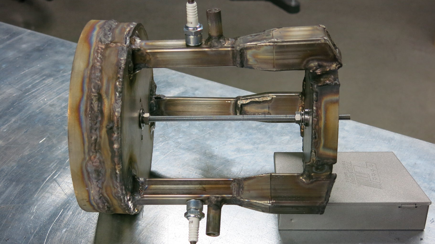
Step 9: Build: Exhaust


The exhaust consists of an end plate, and two sections of bar stock bend into a circle, all welded together. The exhaust turbine goes inside of that housing.
The end plate is made of 3/16" stainless steel plate. This was cut on the water-jet cutter in the Instructables shop, that way all the holes could be perfectly spaced out along the outside. The three square holes needed to be 120° apart, where the exhaust will enter the exhaust turbine.
Because the water-jet cutting didn't turn out perfectly, a few weld beads needed to be placed on the inner circle, to allow the bearings to have a tight fit.
A 6-foot long section of 1" wide bar stock was purchased, and bent into two large rings, using a combination of the metal bender in the shop, a vice, and brute force. The appropriate perfect-circle-making metal bender was not available in the shop.
The exhaust turbine was cut using the Omax water-jet cutter at the shop, after being drawn in Inkscape. It was then placed in a vice, and vice grips were used to carefully bend each blade to a 10° angle. A mark was drawn on the vice with marker to easily identify how far each blade needed to be bent. Ideally, the exhaust gases would come into contact with the blades at a 90° angle. Because this isn't possible with our design, the impact angle will be slightly wider.
Throughout this process, I kept checking to make sure everything fit appropriately. In the pictures you can see a piece of wood cut in the rough shape of a turbine in place of the actual one. This was a test piece used for sizing, to avoid risk of damaging the actual turbine while lining things up.
-
1. Inkscape is an open-source vector graphics creator. If you've heard of Adobe Illustrator, this is like a free version of that program. I'm using it because it's free and available, but feel free to use your vector-graphics editor of choice. Inkscpae is able to save files in *.dxf, which is the format the Omax wants.
Step 10: Build: Intake


The original plan was to use the shroud from the vacuum cleaner motor to snap/bolt on to the engine. Due to the thin walls of the shroud, this wasn't going to work. I was stuck, and kind of scrapped together a shroud using left over 1" bar stock from making the exhaust. The following are directions for what I should have done from the start, and did some version of as I struggled to fix a flawed design.
- Use a laser cutter to mark a 6"x6" piece of stainless steel sheet.
- Use a vertical band saw to cut out as much of the circle as possible, and use a vertical belt sander to smooth out the edges. This will make our "intake plate, similar to the "end plate" in the last step.
- Use a drill press and vice to drill a 3/4" circle out of the center of the piece. This is where the bearing will sit.
- Align the flame tubes, intake plate, and end plate, all together, using the threaded rod that will become the shaft. Weld the intake plate to the flame tubes.
- Using a vertical band saw, cut three, 3-4" long pieces of 1" stainless bar stock.
- Using a hammer and vice, bend each piece into an arch to match the circle of the intake plate as best as possible.
- Place each piece on the engine in between each flame tube, and weld each in place.
Step 11: Finishing Pieces


- Using leftover sheet metal, cut out rectangles, arrange them with a hole in the center, and weld them together.
- Weld three stainless steel nuts to the stainless bar stock portions of the intake shroud made in the last step.
- Drill and tap three holes, aligned with the nuts, so that the sheet metal rectangle can be bolted on to the intake shroud from the last step.
Fuel fixture: Pictures 5-11
This will be used to disperse the propane to each of the three fuel inlets, on each of the three flame tubes, of the engine.
- Drill a 3/8" hole through the center of left over 5/8" stainless rod.
- Cut the rod into four pieces.
- Drill two 5/8" holes in a small pieces of leftover 1" diameter stainless square tube.
- Place a piece of the 5/8" rod in each end of the square tubing, and the two holes that were drilled.
- Weld all the pieces in place
Step 12: Fuel System


We will use propane as our fuel source for the jet engine, as explained previously. The companies who make small propane bottles try really hard to make sure you can't easily get to the wonderful flammable goodness, which makes this part challenging. I first bought a Coleman propane stove regulator, so that I would be sure no propane would leak out of the adapter at the bottle.
The regulator came with a second valve built into the end of the regulator, which I decided to use as a sort of on/off valve. This was accomplished by bending brass rod into strange shapes, and forming a sort of hook-and-latch assembly to slide into the end of the regulator and push the built-in valve open. This involved drilling through the end of a brass elbow, and using epoxy to affix a small piece of brass tube in place so that a gas-tight, yet slideable junction was made.
A variety of plumbing adapters were then used, and epoxied together liberally to form a system of valves and fittings that would regulate the flow of propane with no leaks, and end in a 5/8" hose barb adapter. This entire process was challenging, and there has to have been a better way to do it, but this is what I made work.
Step 13: Electrical System

The "electrical system" of this project is hardly of note. I chose to use an inexpensive stun gun to generate the sparks for the spark plugs to light the fuel inside the engine. Alligator clips were used to connect the output terminals of the stun gun to the connections for the spark plugs. Because the gap of the spark plug is shorter than that of the stun gun, the spark will chose the path of least resistance at the spark plug. The flow of the burning fuel will allow other flame tubes to ignite once the first one is successfully lit.
Step 14: Conclusion

- Math!: Truth is, a great deal of more calculations and measurements probably should have been done before building began. I should have approached this project less as an artist and more as an engineer.
- CAD: For the most part, the extent of my design was done with pencil and paper, and I went ahead and attached my drawings. I reached a certain point in the project where I looked back and it seemed silly why I didn't take the time to learn some AutoCAD to improve the overall quality of my project, and help avoid some bumps I experienced during the build.
Thank you for reading! Feel free to leave a comment, rate this Instructable, and/or subscribe. Getting feedback on my projects is always motivation to keep building and publishing. Thanks!


