

Introduction: Illuminated Neopixel Sign With IR Remote Control


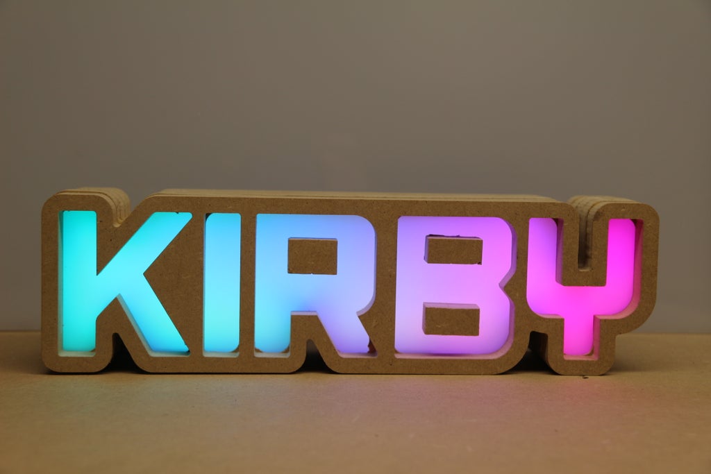
This an LED sign that you can change the colors or animation displayed by using an IR remote. I cut out the design on my Shapeoko 3 in MDF. If you dont have access to a cnc you could also cut these out on a scroll saw. It would just be more work.
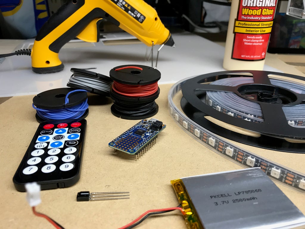
Parts needed
- Neopixel Strip - Comes in a 4m length so there should be enough
- IR Receiver and Remote
- An Arduino compatible board such as a Adafruit Feather 32u4
- Some wires. I really like using these silicone wires, very flexible and comes on a spool
- MDF, I used 1/2" that I picked up at Home Depot
- Acrylic diffuser, I used 1/8" that I salvaged from a wall mounted Xray film illuminator
- Optional - Lipo Battery
- Hot glue gun
- Wood Glue
Step 1: Create Design
First we will create the design of the sign. The animated gif above shows the steps. But we will also go through them more in depth below. I am using Adobe Illustrator but the concept should be similar if using Inkscape or other alternatives.
Create the Text.
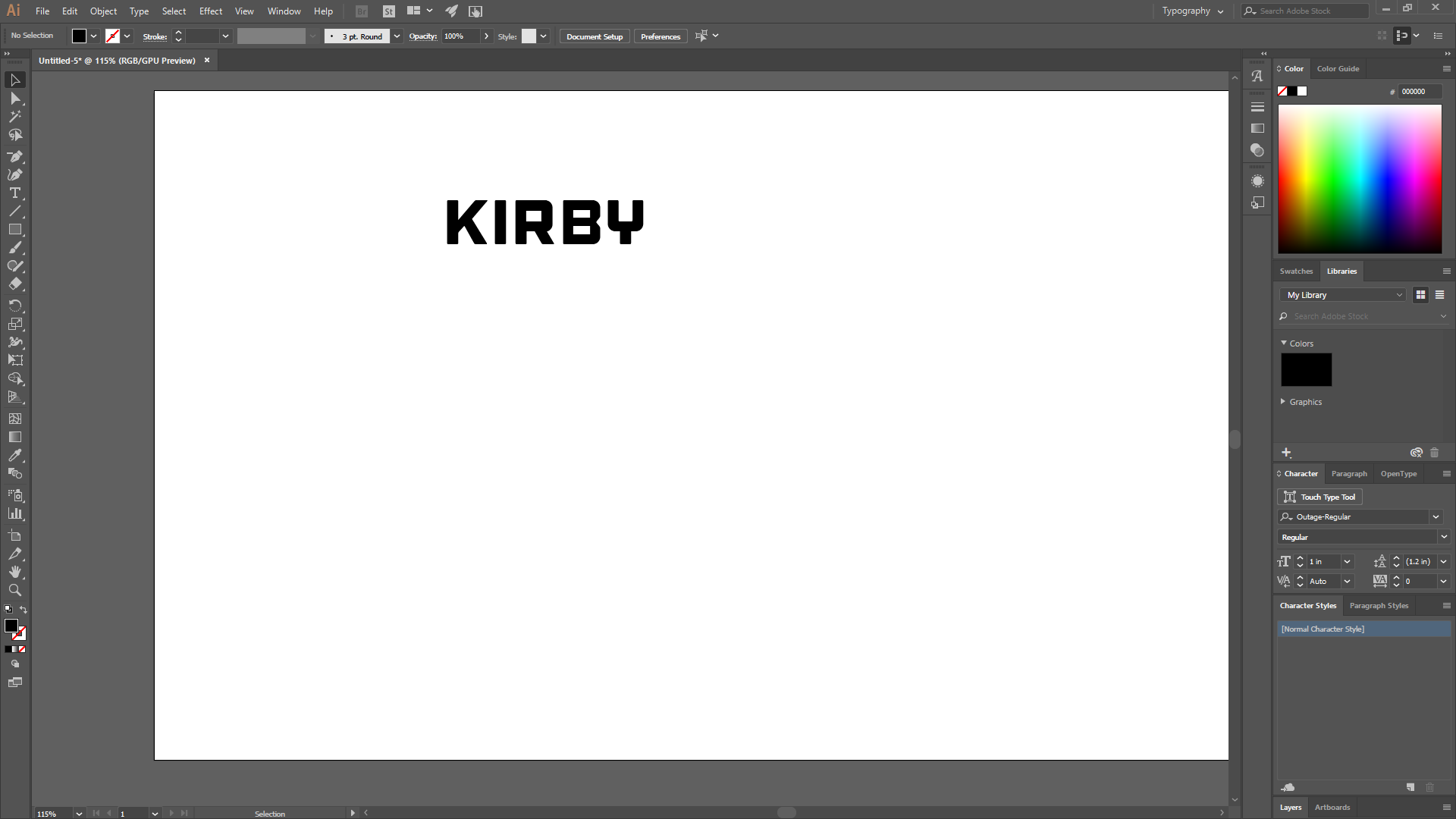
Pick any font that you want. Font size doesn't matter here yet, we will resize it later.
Create Outlines

Right click on your text and select Create Outlines. Now is also a good time to resize to the size you want it to be. Just remember that next step we are offsetting the path by 1/4" so that will add 1/2" to the size.
Offset Path
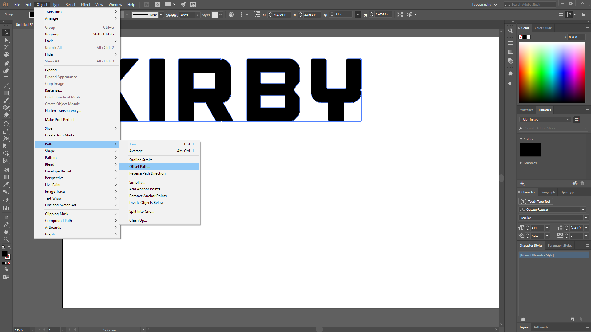
With the text selected, Select the Object menu, scroll down to Path, then Offset Path.
Set the offset

I use a 1/4" offset but you could use a larger one if you want. If the offset paths aren't touching you can go back to the create text step and adjust the tracking of the text to bring the letters closer together.
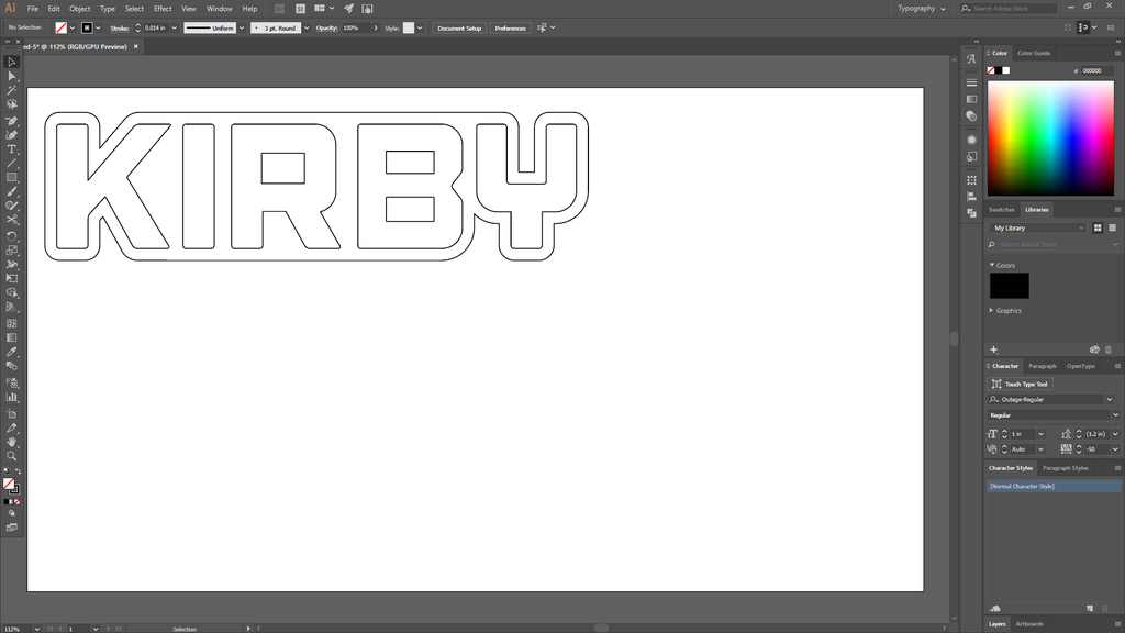
Create a single outline

With the outline still selected click on the Windows menu and then select Pathfinder to bring that box up. Select Unite to create a single outline. I also set the fill to none and stroke color to black at this time. This allows me to see the outlines better.
Now we will right-click on the outline and select Ungroup. Then right-click again and select Release Compound Path
Clean up path

Now we will use the delete anchor tool located under the pen. I went around and deleted anchors to get a flat line one the bottom of the design.
Get rid of others parts

Now is also a good time to delete the other small things not needed such as the small square inside the letter B. I also delete the triangle part between the R and B.
Should look like this
Making copies
Now we will make some copies. On the first copy remove the letters. Then do a negative offset of 1/4". Then make 2 more copies of that. Then delete the offset of one since that will be our back plate.
Inset for diffuser
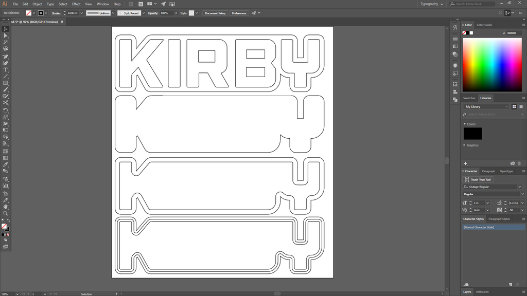
Now we need to make an inset for the diffuser panel. Select the inside line on the bottom copy and create another offset of 1/8".
Create diffuser
To create the template for the diffuser panel we will copy the one we just made the other offset path for. We want to keep the middle path, so delete the inside and outside path. This wont fit in the inset on the wood since the dimensions are the same. We will do another offset path, I used -1mm. Then delete the outside path.
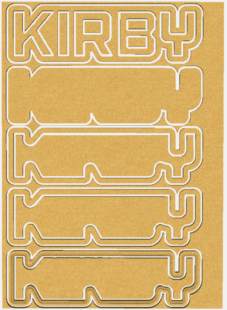
You now should have the designs for cutting the parts. One top layer with the name, a diffuser, layer with inset to hold diffuser, layer with cutout - you may want to use two of this layer, and a bottom layer.
Step 2: Cutting the Parts and Assembly
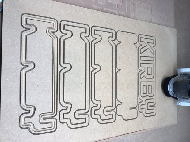
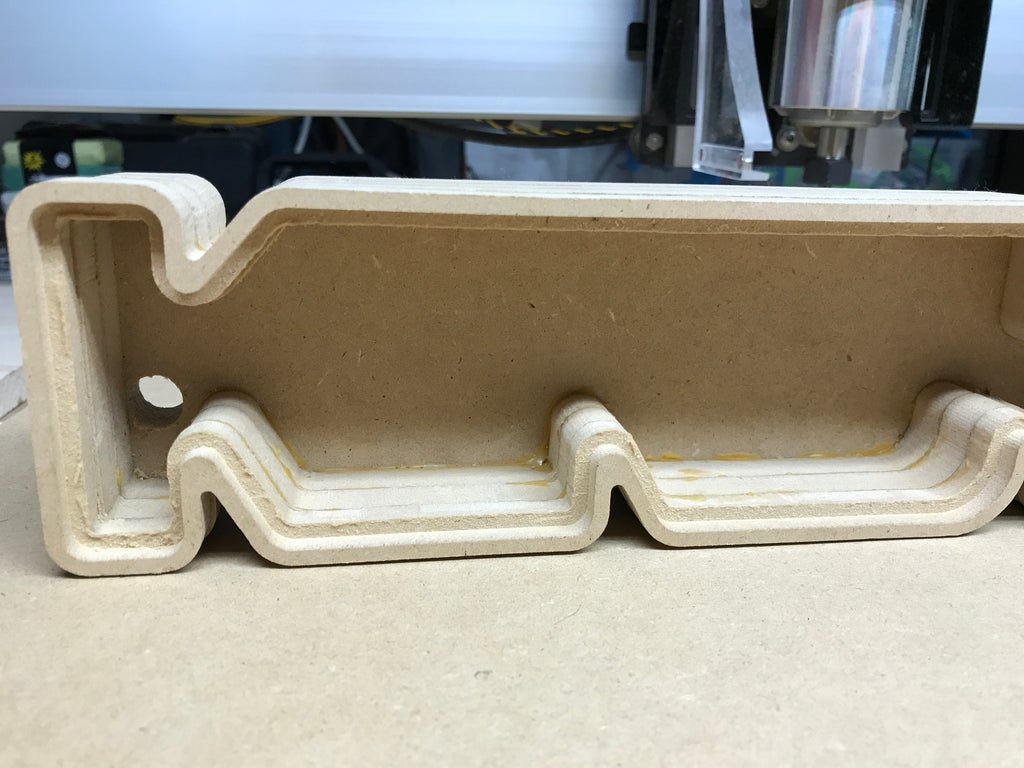
In the program you use for your CNC Router you want to cut the outlines of the layers to the depth of material along with the letters and inside line from the spacers. When at the layer for holding the diffuser you want to have an inset depth at the thickness of your material.
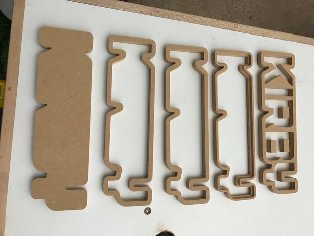
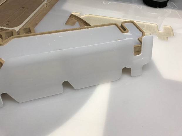
Remove from board
Now that the parts are all cut out you can remove them from the MDF sheet. Mine did not remove easily since I didn't have the Shapeoko cut deep enough. Newbie mistake since I am still learning it. I took it over to the scroll saw and cut them out and then cleaned up the edges on the router table with a flush cut bit.
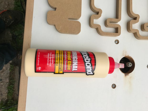
I used some wood glue for gluing the parts together. I used the regular version since it was cheaper and was only going to be used inside. Try not to put too much down so there is less cleanup and sanding later.
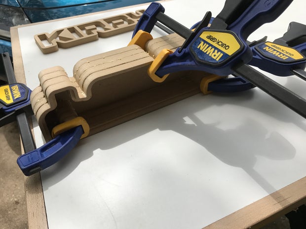
Leave the top layer out since we still need to put the lighting in and the diffuser layer. I used a few clamps to hold it together while the glue dried. Try aligning them better than I did, saves from sanding later.
Once the glue has dried you can drill a hole for the LED strip wires to go through.
It is also a good time to check that the diffuser fits well.
Step 3: Add the LED Strip
To determine the length of LED strip is needed I used a cloth tape measure. You could also just use the strip but be careful not to twist it too much and possibly damage it.
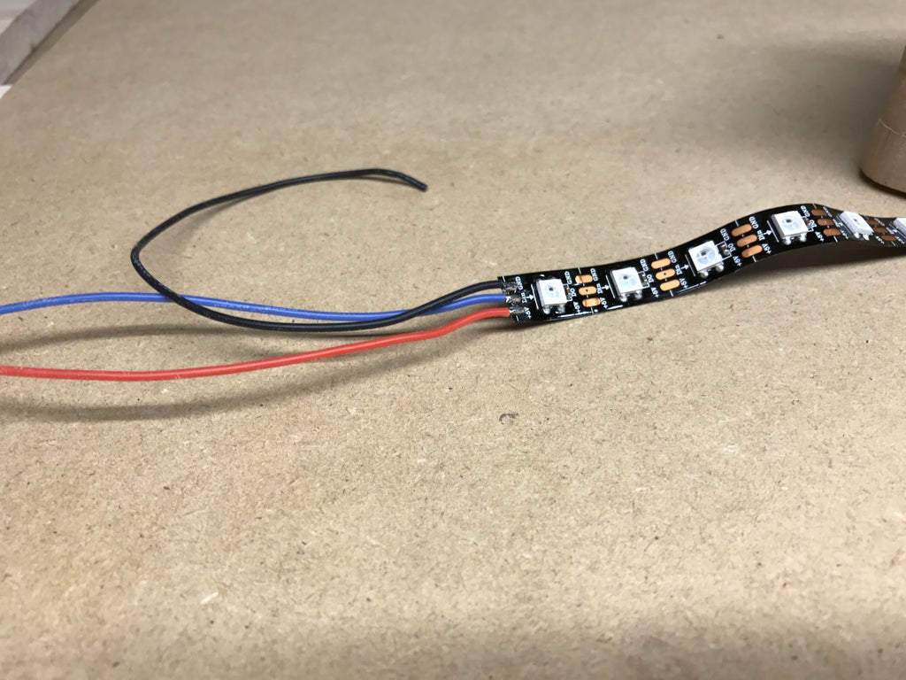
Once you have the correct length I removed the soft rubber sheathing that was around the strip. I also then soldered some wires to reach the Feather board.
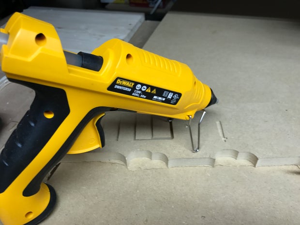
I used hot glue to attach the strip.
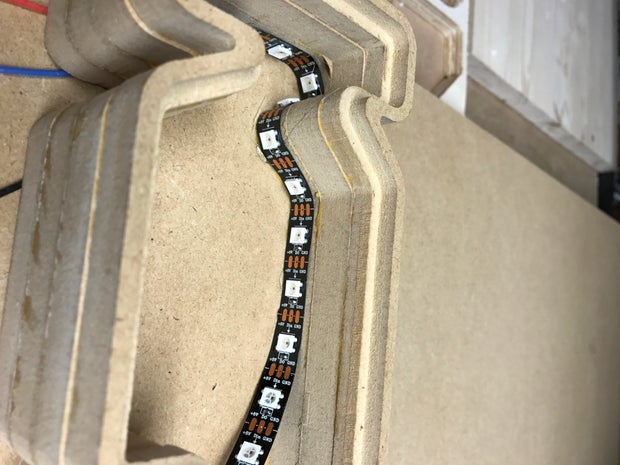
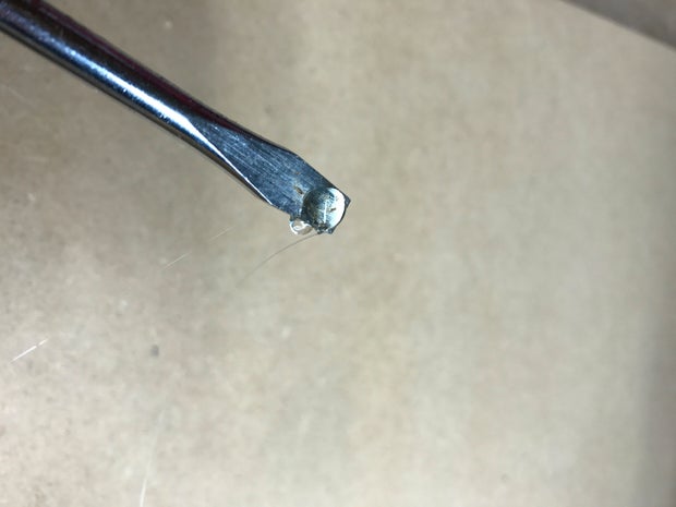
Sometimes a section is too small to reach with the hot glue gun. For those I put a bit on the end of a screwdriver and use that to place it.
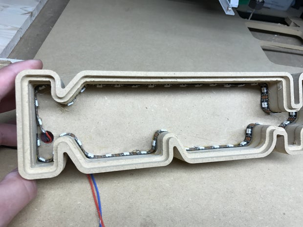
Here it is with the strip fully glued down.
Step 4: Add the IR Reciever
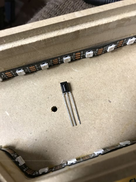
We need to drill a hole for IR Receiver leads now. I kept mine centered on the design.
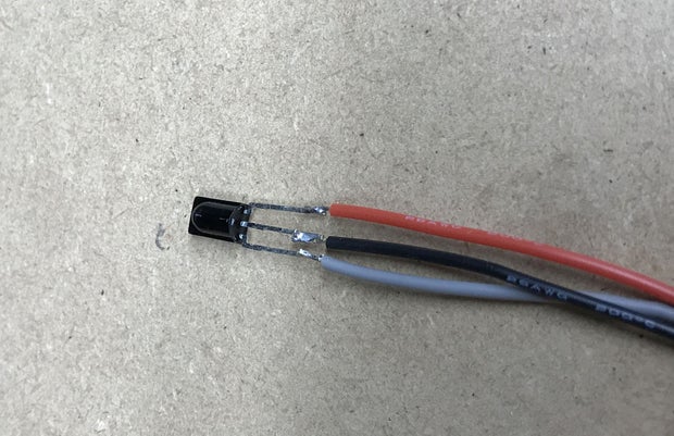
Also a good time to solder on some wires to the leads, make sure they are long enough to reach the Feather board
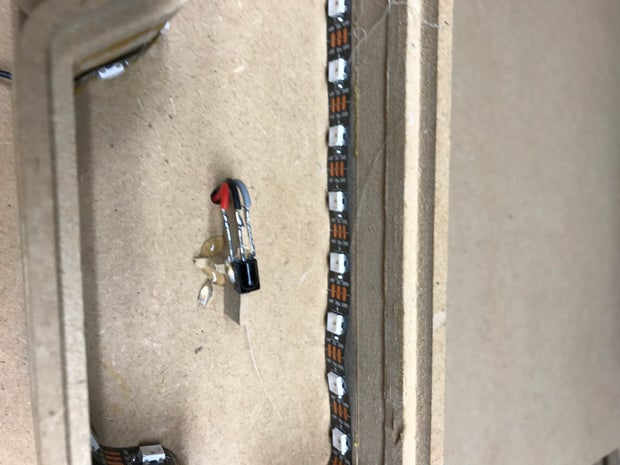
I hot glued the receiver on a piece of scrap to raise it up a bit. Make sure the domed part of the receiver is facing the front.
Step 5: Wire It Up
Fritzing Diagram
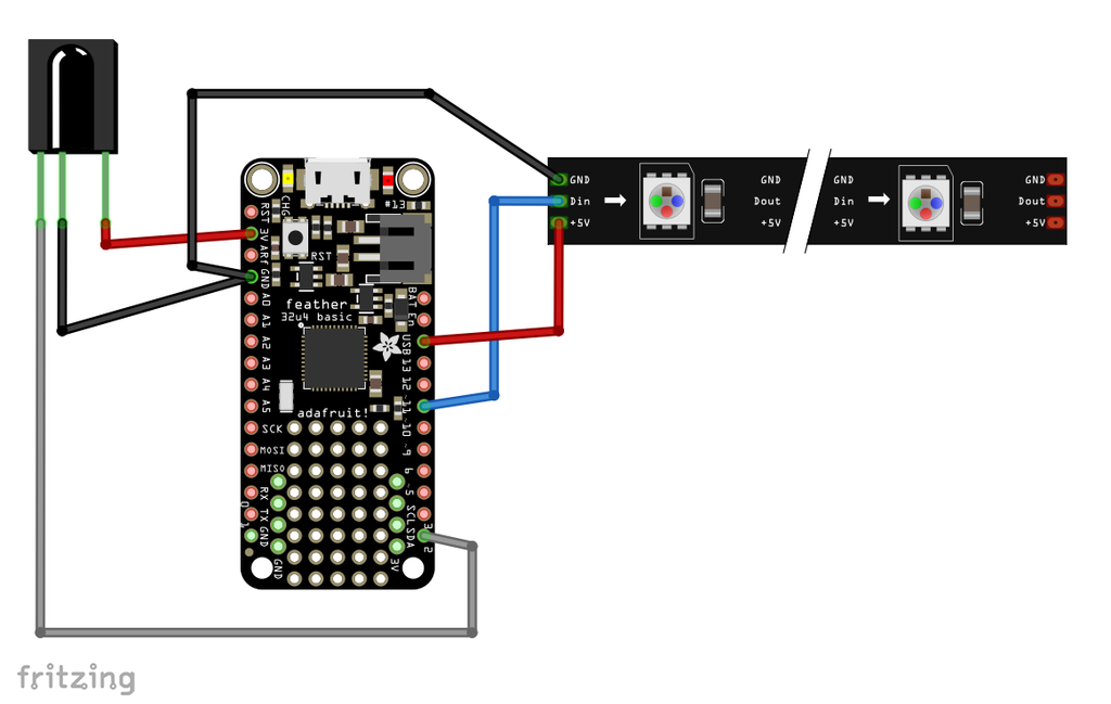
Wiring this up is pretty simple. Only a few connections
Neopixel strip
- GND to Feather GND
- +5V to Feather USB
- Din to Feather Pin 11
IR Reciever
- Pin 1 to Feather Pin 2
- Pin 2 to Feather GND
- Pin 3 to Feather 3V
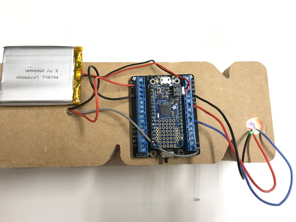
The connections should look like the above image. I used the Terminal Block FeatherWing to make testing easier without having to solder the connections to the Feather. This part can be skipped and soldered directly to the Feather.
You can also optionally use a Lipo battery with this to run on battery power. Any of the ones sold by Adafruit are compatible with the Feather. The Feather has the circuitry built in to charge the battery also.
Step 6: Put the Code on It
If you are unfamiliar using the Adafruit Feather 32u4 I would suggest following the tutorial on the Adafruit site first and verifying the board works with your Arduino IDE and that you successfully load the blink sketch.
You can then load the code provided below on the board. On line 14 you will need to change the value for #define PIXEL_COUNT to be the number of Neopixels on your strip. I had 48 on mine.

Step 7: How It Works
When turned on it will always go to the first color in the code. For the provided code that is Red at full brightness. You can then cycle through the colors by pressing the right arrow on the remote. If you press the left arrow it will change to animated. Pressing up on the remote will change the speed of the animation.
To go in to low power mode where it turns off the color press VOL- on the remote, to turn it back on press VOL+.
If you press the enter button it will do a nice rainbow animation for a bit.
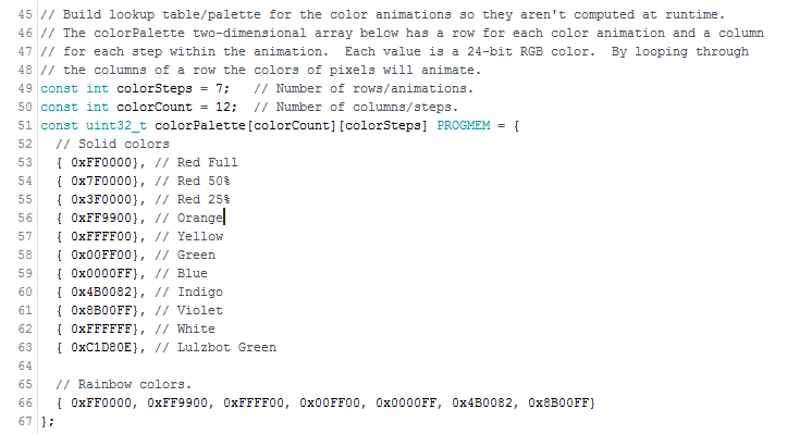
If you want to change the colors or the order you can alter this section of code. If you add or remove a color make sure to change the value for colorCount to match. colorSteps is the amount of colors in the longest string, which in this example is Rainbow Colors. When not in animation mode Rainbow colors will just show the first color which happens to be red.
You can also add another color to Green such as Blue so when in animation it has those two colors.
To find some colors you can use an online color picker such as this one.
Step 8: Final Thoughts
Overall I think this came out pretty good for my first try. A few things I would do different on the next one is add holes for a dowel so I can align the layers up better when gluing together. I would also like to spray some filling primer and sand it smooth and paint it a different color. For the top layer use a nicer looking wood than MDF and apply a nice stain to it.
Credits
I got the inspiration for this from a YouTube video I saw by Michael Curry titled Making an Illuminated Sign with Inventables X-Carve and Adobe Illustrator. When I saw that I thought it was cool but wanted to improve on it by being able to change the colors. I also thought a step by step description would be good.
I also wanted to thank Tony DiCola for the Techno-Tiki RGB LED Torch which I was able to modify the code to work with this.

Participated in the
Lights Contest 2017

![Tim's Mechanical Spider Leg [LU9685-20CU]](https://content.instructables.com/FFB/5R4I/LVKZ6G6R/FFB5R4ILVKZ6G6R.png?auto=webp&crop=1.2%3A1&frame=1&width=306)


