

Introduction: Logic Probe W/display


This project is equipped with 5 Not Gates, 1 transistor, 8 resistors, and 1 Common Anode Display. The Logic Probe w/display is a project for identifying Zero (0) or Low, One (1) or High, or Pulse. For Zero, you will see illuminated the upper side of the display by simulating a "0" (Zero). For One, you will see illuminated the rest of display for forming a "P" without illuminating the upper side of the display by simulating a "1"(1). Finally, for a Pulse, you will see illuminated the display by forming a "P"(Pulse). And so you can detect "0's", "1's", and Pulses.
Step 1: List of Materials

The list of materials is the following:
1 Prototype Board
1 Green Display CA
1 7404
1 IC-socket 14-pin
1 Transistor 2N3904
5 Resistors of 330 Ohm
1 Resistor of 470 Ohm
1 Resistor of 10K Ohm
1 Resistor of 1K Ohm
1 +5V Standard Regulator
2 Electrolytic Capacitors of 47 microF, 50V
1 Battery Clip, For 9 Volt
1 Test Leads, Banana, 42 inches, 1 Red, 1 Black
1 Binding Post, Breadboard, Screw, Type, Chassis Mount, 1 Black, 1 Red
9 V Battery is not included
Required tools or supplies:
Soldering iron
Solder
Wire stripper and cutter
Needle nose pliers
1 Jumper Wire Kit (Radio Shack Part # 276-173)
Step 2: Install the Components


Step 3: Complete Your Project


9 Volt Battery is not included
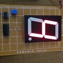
Step 4: Logic Probe W/display in Action


Probe Digital Circuits
The sequence of pictures:
Low "0"
High "1"
Pulse "P"

Participated in the
Make It Glow


