

Introduction: Making a $70 Glass Etching Tool for Less Than $10 Comparable to the Air Eraser


Question;
Can you create a safe, effective, air powered, glass etching tool, that is comparable to air eraser for under $10 and using materials readily available in any home?
This instructable is in response to the many people who've had a difficult time finding the Paasche air eraser (or clone model) and is a sister tutorial to "Etching On Any Surface Cheaply And Without The Use Of Chemicals". As well as extensive photo's, I plan on adding brief vids to try and clearly explain my process.
As an air tool, the air eraser is extremely complex, and beautifully constructed. As such, it'd be nearly impossible to duplicate it exactly, however , with some basic supplies, and some lateral thinking, we can apply some of the principals of the air eraser to an effective etching tool of our own.
The fundamental goal is to simplify. With some expensive parts, and a well stocked workshop, I'm certain that a high grade etching tool can be fabricated, however most do not have access to a shop, and are often limited to items scavenged from around the home.
This instructable is for those folks.
Step 1: Converting the Air Eraser to Theory


There are three methods that I want to look at. They are not, by far, the only way to create the etching tool, such as using suction, etc, however, as our intent is to keep the project as small as possible, they are the most practical for our needs.
Fig. 1 - Air is fed in and passes through the body of the tool. The etching compound is gravity fed, like an hour glass, into the body and is picked up by the air flow.
Advantage - Simple design, easy to construct
Disadvantage - Uneven flow as air will inevitably push the compound back up into the resevoir restricting flow.
Fig. 2 - Air is diverted through the resevoir base, agitating the compound into a mist, then blowing it through a down tube to the tip.
Advantage - Better flow as tool will not need to be shaken to keep a constant flow of abrasive.
Disadvantage - Higher, possibly unsafe pressure. As air turns corners, it slows and thus pressure needs to be raised to compensate.
Fig. 3 - Same as Fig. 2, however a second air line line is diverted to the tip of the tool.
Advantage - Lower pressure. The compound is agitated, as in Fig. 2, and the second line acts as a 'booster' accelerating the compound as it leaves the tip.
Disadvantage - More difficult build. More intricate parts means more problems.
**Important Caveat - As usual, I have to give fair warning. The basis for my design is low, safe pressure of, up to 45psi. Exceeding that, while using makeshift parts could be hazardous and is highly unrecommended. If you choose to build fig. 1 or 2, you do so at your own discretion, however, you have been warned.
Step 2: Testing Various Parts for Our Build


In creating the tool, I had to break it down into three parts; The air supply manifold, the reservoir, and the delivery system. I don't plan on giving a definitive parts list, as the supply of materials from one person to the other can differ greatly. Rather, I intend on looking at the tool as a series of problems and concepts, in hope that each person can, independently come up with solutions on their own.
Of the three, the delivery system was the easiest to duplicate. In essence, the tip acts as a bottleneck, taking the flow of compound and air, and restricting them, not unlike the spray nozzle on a water hose. As you can see from the second pic, this was accomplished by using the tip of an ordinary pen, and pressing two hoses side by side, then sealing them in place with some 5 minute epoxy. The smaller of the two lines goes directly to the manifold, and the larger is our feed tube for the compound in the reservoir. The white tip, on the smaller line is simply a pen part that I used as an adapter to fit both lines into the tip.
The reservoir was the second easiest, and was dependent on what I could come up with for the manifold. One line is fed through the lid and acts as the down tube for the compound being fed to the tip. There needed to be another air line coming directly from the manifold that agitates the compound and forcing it down through the down tube.
Finally, the hardest part was the manifold. This went through a lot of variations. In essence, I needed to split the flow of air between the reservoir and the booster tip. Unfortunately, I didn't have the material to create an adapter manifold with two outlets, and so decided to feed my air supply directly into the bottom of the reservoir, with a second line passing through the bottle itself, and exiting through a different hole, in the lid, and attaching to the booster line. The advantage of this is that there are no angles to slow down the air flow. Think of a water slide with a 45 degree turn. There's an abrupt (albeit painful) stop then the turn. What I've done, is more like a bobsled track. Tho there are curves in the line, it doesn't abruptly slow the flow of air, and there's no pressure lost.
Step 3: The Final Form and the Results of Our Experiment


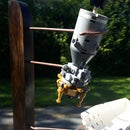
In pic one you can see the final form of our manifold. it's simply an adaptor with one air outlet, and a second hole drilled, at angle beside the first. An air line is attached to the stem, and the entire piece is mounted to the bottom of our reservoir (bottle lid).
In the second pic, you can see the final assembly. As mentioned, the air nozzle is mounted directly to the base, with the booster line passing through the reservoir, and eliminating the need for a manifold. The air line doesn't affect the operation or flow of compound and actually is a benefit as there are no angles to slow the flow of air, allowing us to operate at lower pressures.
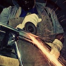
Step 4: Testing Our New Air Eraser

Here's a short vid of the test for confirmation;
Step 5: Conclusion of Our Experiment
I used some pretty makeshift parts in the fabrication of this tool, however it functioned beautifully and should be easily duplicated by anyone, regardless of how equipped their workshop is. As mentioned, before, there is no definitive parts list, as I just used random pieces I had laying around the house, but that's the point. Whether you have few supplies, or access to vast amounts of hardware, you can recreate this tool using the principals I've outlined here, and in fact, could end up being the very person that improves the design making it both essential, and affordable to the average crafter.
I hope you enjoyed the instructable. Thank you for following.

Participated in the
Scientific Method Contest


