

Introduction: Modbus Mach3 to Arduino(no Additional Hardware) + Brain Setup


I will describe here how to connect arduino directly to mach3 without any additional hardware.
This will not use any modbus library it is just proof of working. You will end up with ability of mach3 to read input pin on arduino. But if this will work for you then adding full modbus library for proper comunications shouldnt be any problem.
Small think about modbus
Modbus is software protocol not hardware, so you can use it not only ower rs232 or rs485 but also let say uart usart. Doesnt matter the amount of connections the hardware protocol uses, basicaly it boils down to one comunication line for half duplpex and two for full duplex.
The comunication of mach3 with arduino will be done using uart. so rx tx lines.
In this case the standard Usb cable connecting pc and arduino will do.
But you can buy USB to rs485 adapter and connect to rx tx lines and it should be basicaly the same think.
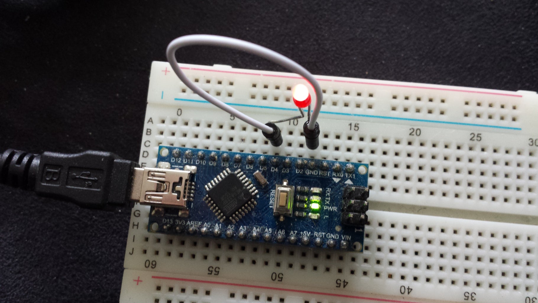
On the image is the whole setup. Arduino connected to PC + one led but you dont need the LED (it is just indicator so i know what information should be send back from arduino) and cable so you can ground a pin on arduino. Led should have resistor in series, i just coudnt be bothered and the led suvived.
On left side of image is the USB to rs485 adapter (you dont need that). i just wanted to add it in case you wanted to know what the one i have looks like. and it works fine. i was trying it with some rs485 hardware.
Step 1: Owerview of Concept
I did my test with arduino mini pro.
This was the inspiration for my test and the code is from this page: http://www.machsupport.com/forum/index.php/topic,2...
First software for arduino:
The whole think is very simle, arduino recives in this case any 8 bites and replies with
01 04 02 00 00 78 f0
or
01 04 02 00 01 b9 30
In real comunication these packets are modbus reply for "01 04 00 00 00 01 31 ca" question. which is read input register question.
So we will send request from mach3 to read input register and arduino replyes with data containing 1 or 0. So thisway we can read state of inputpin on arduino.
quick look at the modbus package:
let say thisone: 01 04 02 00 00 78 f0
- 01 is addres of slave device
- 04 is information that we are going to read input register
- 02 00 00 lets simplyfy this for the data information. ( but basicaly it is N*8bits of data in this case so 2 bit containing 00 00)
- 78 f0 is just checksum
so mach3 will read from thees returned packets
01 04 02 00 00 78 f0 returned ingormation is 0
and from 01 04 02 00 01 b9 30 returned ingormation is 1
Step 2: The Arduino Site Step 1

We will need some Modbus tester : KMtronic_ModBus_Tester
http://info.kmtronic.com/kmtronic-modbus-relays.ht...
We upload the code at the bottom of this page to the arduino.
Attached image is from the tester it will automaticaly show you port on which is arduino connected if you have more ports connect and disconnect arduino you will see which port dissapear and then appeard in the list again.
set comminication speed for 9600 as this is what we use at the mmnt in the serial comunication in arduino program.
and to comunicate with arduino you need to click Open. this will connect you to device and allow for sending and recieving information. When the Port is open no other program can communicate to arduino you will need to CLOSE it first.
This code is basicaly copy form the page i used as inspiration. i just added the LED. because i needed small help with testing. and changed pins.
int pin = 4;
int pinLED = 5;
int in_buffer[8]; // receiving buffer
int reply_1[] ={0x01, 0x04, 0x02, 0x00, 0x01, 0x78, 0xF0};
int reply_0[] ={0x01, 0x04, 0x02, 0x00, 0x00, 0xB9, 0x30};
void setup() {
Serial.begin(9600); // Init serial communication
pinMode(pin, INPUT); // Set pin to input
pinMode(pinLED, OUTPUT); // Set pin to input
digitalWrite(pin, HIGH); // Turn on pullup resistor
}
void loop() {
//just an led information if input for which we test is high or low
if ( digitalRead(pin) == 0 ){
digitalWrite(pinLED, HIGH);
} else {
digitalWrite(pinLED, LOW);
}
if ( Serial.available() == 8 ) { // read ModBus command from Mach3
// in this example we only read, don't check anything
for (int i=0; i < 8; i++) in_buffer[ i ] = Serial.read(); // Read Input PIN and reply with 0 or 1
// Reply is inverted because PIN default state is HIGH and we connect to GND
if ( digitalRead(pin) == 0 ) {
for (int i=0; i < 7; i++) Serial.write(reply_1[ i ]);
}else{
for (int i=0; i < 7; i++) Serial.write(reply_0[ i] );
}
}
}
Step 3: The Arduino Side Step 2


Now we send request command to arduino 01 04 00 00 00 01 this is what mach3 will do.
We could send any 8 bytes to arduino as you can see from program , it is just to properly answer so arduino doesnt care for question in this case.
also note that we send this : 01 04 00 00 00 01. tha last 2 bytes which is checksum will be automaticaly added by the Mddbus tester program.
On the image is possible to see that i sent twice the 01 04 00 00 00 01 command to arduino.
- first in red rectangle:
when D4 pin is not connected to anything (is sitting at 5v)
0-TX 01 04 00 00 00 01 31 ca is what arduino recieved
and replied with the 1-Rx....... returning 0 in the data
- then the green rectangle
when i connected D4 to ground, my LED is on now
and reply is 3-RX...... returning 1 in data
if this works for you, then the arduino side is done. as we can see arduino replying to questions sent from the tester.
the last two images are the arduino setup when set to reply 0 and then set to reply 1.
Step 4: Mach3 Side 1

First in your modbus tester press CLOSE button. Otherwise Mach3 will be unable to communicate with arduino (it will not be able comunicate on already OPEN COM port).
go to mach3 top menu-> config -> ports and pins
tick both options as seen on image.
you will need restart Mach3 for this change to be applied.
Step 5: Mach3 Side 2

In Mach 3 go to top menu->setup serial modbus controll and in popup window press test modbus.
Mach3 will not add automaticaly any choice for Port Num.: but this will be the same port you have seen in the modbus tester application so if it was showing Com5 write in Port Num.: 5.
set comunication speed for 9600baud
As usualy you need to pres OPEN to allow for communication on the com port.
if there will be something wrong Status: message will show you. otherwise there should be written : No error
Now you can basicaly set rest of the data as on the image
when you press Read button: in the big data window on the right it should show 0000.
then when you coonect on arduino D4 to ground and pres Read button in mach3 again it should display 0001.
now you have succesfully established comunication with mach.
Step 6: If Any Trouble


I am using a software called free-serial-analyser.
this will show you what is sent or recieved on given comport.
look at the images to see how i set the viewer.
The last image shows you the window where you can check the communication.
you can see what data are sent from mach and what arduino replyes.
you can see arduino replying by 0 and then 1. that is what you should see if you done the test in previous step.
if you are missing some data you can quickly here identyfiy if mach is sending something or if arduino is replying.
Step 7: Real Use of the Comunication

Set the proper com port (i am bit messy on the images sometimes i have 4 sometimes 5 but if you dont unplug and plug in other devices the port will be the same) on which your arduino is connected and fill the data as per image.
this config will set CFG #0 be sending request to arduino to read the input register.
if all is set correctly and you pressed apply button the arduino rx tx led should be constantly blinking as mach is sennding the requests in 50ms intervals (refresh column)
Step 8: Setup Brain 1
Go to top menu->operator-->brain editor.
it will asks you for the bain name so give it some. then it will open the editor.
on my image it is all filed in already but:
you will press +
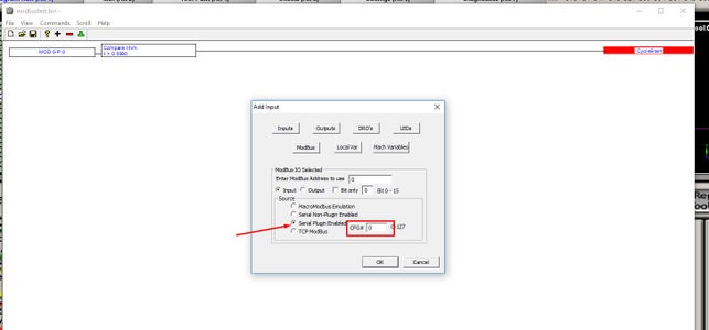
and winndow add input will popup. where we add the "input functionality"
in the window press modbus and do the setup as per image.
you are just setting for the fact that you are using modbus plugin and and the CFG #0 which we set in previous step.
Step 9: Setup Brain 2

now select the first added rectangle and press + again
it will give you different window so just press ok for no operation
Step 10: Setup Brain 3

Now select the second added rectangle and press the upside down T this will add the functionality what should happend when the signal recieved is 1.
simple way is to just add button press and start cycle.
and now when 1 is recieved from arduino it will start your program.
not yet but it will..
you can save your brain now.
Step 11: Setup Brain 4


Go to the top menu ->brain control
select your brain and press enabled and hit ok.
not sure but you might need restart the mach3
then come back here again select your brain and press view brain.
Step 12: Setup Brain 5

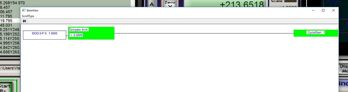
You should be able to see the response of the brain when D4 on ardino is connected to ground or not.
TADAAAA functional mach3 comunication which acts as remote Cycle Start button.
hope you liked it.


