

Introduction: LED Matrix Installation in Old Electronics Case - Requires Kit Purchase


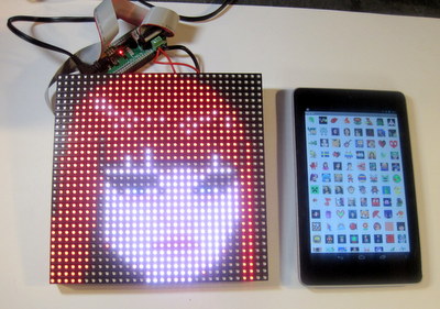
The LED display controlled from a Windows PC over Bluetooth and LED diffusion techniques
Step 1: Assembly


While scrounging at a local electronic surplus store, I came across this enclosure which used to be some sort of graphing charting device. Just my luck, it fit the LED panel perfectly.
After removing the inside metal plate, I used this template to drill holes to mount the LED matrix. The LED matrix has 8 mounting screws on the back of it. The mounting template shows the placement of the 8 screws on the back of the LED panel as well the cut-out needed for the LED panel header and power cables. Use (8) 4-40 x 5/16″ pan head screws (not included in the kit) for mounting.
Here's also a generic mounting guide for the kit.
You'll also need to cut a rectangle cut-out (also in the above template) for routing the cable to connect the LED matrix to the IOIO board.
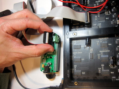
Then it's just a matter of connecting the ribbon cable (included in the kit) from the IOIO board to the LED matrix and mounting the board inside the case (hot glue used in this case).
The whole project is open source. If you can code in Java, then you can leverage PIXEL's SDK to add in new functionality.
PIXEL Maker's Kit
PIXEL developer information ==> Link
Source code for Android ==> Link
Source code for the PC application ==> Link
Special thanks Ytai Ben-Tsvi, creator of the IOIO board, for all his invaluable help on this project and to Roberto Marquez who developed PIXEL's PC application.
Step 2: Setting Up the Kit

Step by Step Guide for the PIXEL Guts DIY Kit
| Included Parts | Specs / Info |
| 32x32 RGB LED Matrix | 1024 RGB LEDs, 190mm x 190mm x 15mm (7.5" x 7.5" x 0.625"), 1400 cd/m2 brightness LEDs on a 6mm pitch, 1/16 scan rate, Data sheet (partly in Chinese) |
| IOIOMint Board + LED Matrix Shield | Specs |
| Bluetooth 4.0 Dongle | Plug this dongle into the iOIOMint board's USB port |
| Bluetooth Dongle | If using the PC app, plug this dongle in your PC's USB port. Not needed if using Android as Android has Bluetooth built-in. However, if you have an older Android device, you may need to use this dongle instead and plug into the IOIOMint board USB port. |
| Power Supply | 110V to 240V power supply. Outputs 5VDC up to 4 Amps. Standard 2.1mm barrel jack connector. The power plug is the "two-prong style" for US/Canada/Japan so you'll need to supply your own adapter for other countries. |
| Cables | LED Matrix Data (IDC) and Power Cables |
PIXEL Guts Setup - Video Tutorial
This video tutorial (running time: 8:15) walks through the setup of PIXEL Guts as do the step by step instructions below.PIXEL Guts Setup - Step by Step Instructions
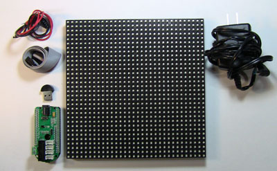
| PIXEL Guts includes a 32x32 RGB LED matrix, IOIOMint board + LED matrix shield, Bluetooth dongle, cables, and power supply. | |
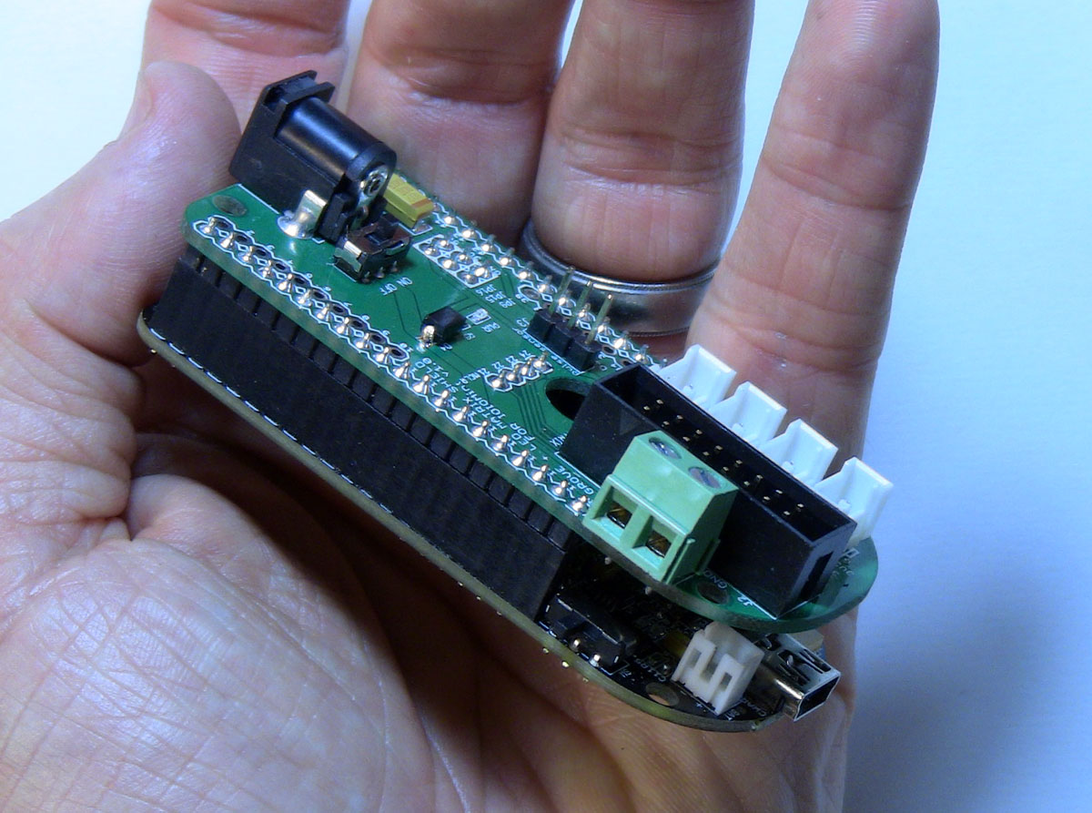
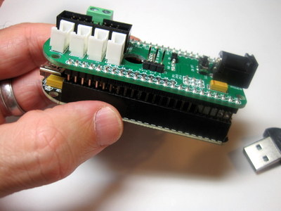 | Snap together the shield (green board) to the IOIOMint board (black board). | |
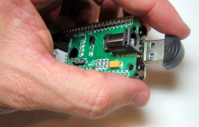 | Plug in the Bluetooth dongle | |
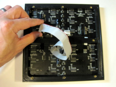 | Flip over the LED matrix and plug in the cable. Note the two up arrows etched on the side of the LED matrix. Ensure those two arrows are pointing up. Plug in the cable to the connector on the left. The cable connector is notched and will only go in one way. The connector on the right will not be used. | |
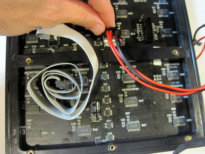 | Plug in the LED matrix power cable. This cable also only plugs in one way. | |
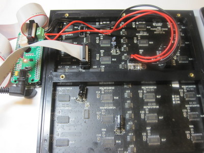
 | Plug the other end of the LED matrix cable to the board. Just like on the LED matrix side, the cable only goes in one way. | |
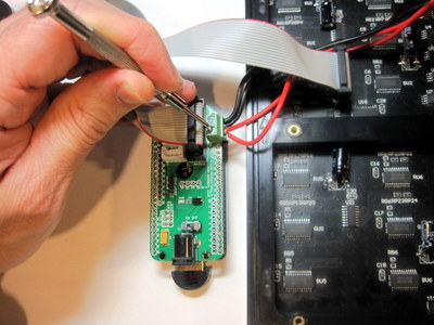  | Screw in the other end of the power cable from the LED matrix to the board. This end of the cable doesn't only go in one way so pay very careful attention that the red wire goes next to the 5V label and the black wire goes next to the GND label as shown in the picture. | |
 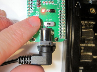 | Plug the power supply into an AC outlet and then plug the power jack into the board. Turn on the board using the switch, the red LED will turn on. | |
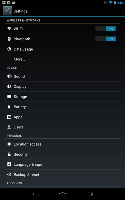 | Congratulations! You've got the hardware connected and powered. Now let's get the hardware talking to your Android device.From your Android device, go into Android settings. Tap "Bluetooth" and then search for Bluetooth devices. | |
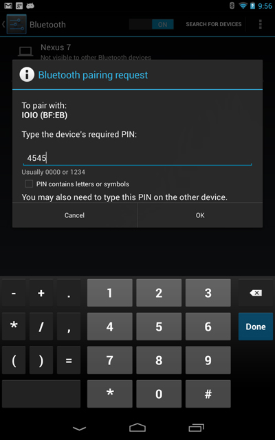 | You'll see a device called "IOIO". Tap on "IOIO" and enter "4545" to Bluetooth pair. | |
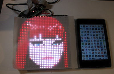
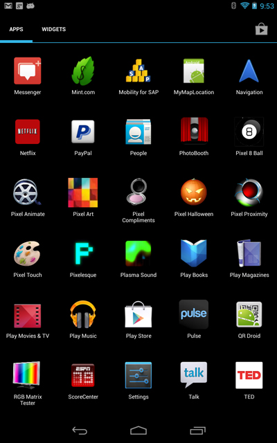 | After downloading PIXEL's apps from Google Play, launch the "PIXEL Art" app. | |
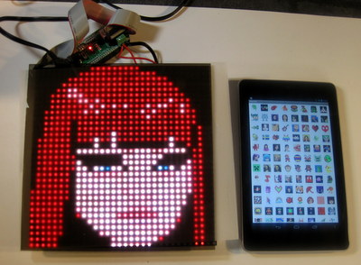
 | Tap an image to display it on PIXEL. | |
 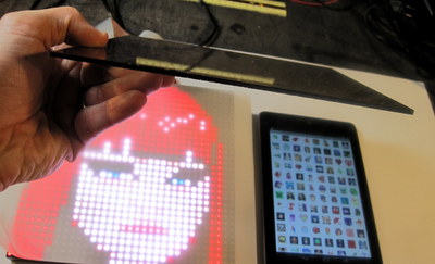  | All Done! Now it's your turn to install PIXEL Guts in some cool way. If you don't mind sharing, we'd love it if you posted your installation on PIXEL's facebook page. Note that you'll get better resulting by diffusing the LEDs by using a thin layer of parchment paper and/or acrylic sheet. | |
| Optional - If using the IR proximity sensor to enable PIXEL's interactive applications, you'll plug the IR proximity sensor into the top white connector. |
Step 3: More Videos
Scrolling Text

Participated in the
Instructables Green Design Contest

Participated in the
Epilog Challenge V


