

Introduction: "Room-duino": Controlling Your Home Device From Internet, a Home-brew Arduino Solution


I recently designed “Roomduino” to control electrical devices in my room from internet, it's a solution base on Arduino, I custom designed two boards for the small system, the first is a "network gate" board, which is like a hub or a master node, built by an Arduino compatible board and an ethernet board. the second board is a "network node" board, which is a electric switch board with 2.4GHz RF board for communication with "network gate", it controls electric switchs of your devices. A "network node" board must be fit into your electric socket, a DIY work is necessary in this step.
the hareware part of "Roomduino" is the most difficult part comparing other steps in this design. I have described 3 alternative solutions here for your reference. in "hareware solution 1 and 2", you need to custom made PCB boards for the system. however, in "hardware solution 3", I used Microduino to build a "network gate", it's the simplest way to build your owner "master node". Microduino is a kind of very small Arduino compatible board and supplys a plenty of extension modules, you can just stack the boards together to build your own "homeduino", please check http://wiki.makermodule.com, or https://www.facebook.com/Microduino for details.
opensource codes are shared in this instructable.
My lamp, water machine, fans and curtain are connected to “Roomduino”, then I can use my cell phone or a webpage to remotely switch the devices, it’s really a cool experience.
I've written up my method so people can make their own.
===========BOM===========
1. Network Gate (Master)
• MCU: MEGA644PA (MEGA328PA is SRAM is not sufficient to support it)
• ETHERNET: ENC28J60,RJ45(HR911105A)
• WIRELESS 2.4G: nRF24L01
• DISPLAY: NOKIA5110 or OLED 12864
• REMOTE CONTROL: Infrared remote controller + infrared receiving head for remote control
2. Network Node (Slave node)
• MCU:MEGA328P or 168PA;
• WIRELESS 2.4G: nRF24L01;
• Electric relay, BT136, MOC3041;
3. a network router
4. a YEELINK.com account for internet control (a public cloud service), yes, you can use other cloud servers as you like, please remember to revise the software accordingly.
5. Software: I put all source codes in github: https://github.com/wasdpkj/Roomduino
===========System Spec===========
Features:
• Infrared remote controll
• A RTC to schedule electrical switcher (electric relay)
• Remote controller via internet, support multiple control methods:
o Use webpage to control the system in LAN scope
o Use Yeelink.com to control the system in WAN scope (internet)
• Currently, the system only can control four channels, because of the limitation of Yeelink.com
1. Automatically time synchronization through network
2. ETHERNET POE
3. 2.4G wireless controll
4. Allocate the I/O for DHT11,18B20
===========System Limitation ===========
• Current "Roomduino" system only support Google Chrome in LAN wide, , it is because of the limitation of “jquery”, for security reason. Check more details in github documents (web.rar): https://github.com/wasdpkj/Roomduino
============
Author: https://www.facebook.com/pan.kejia
Editor: https://www.facebook.com/Microduino
Step 1: [hardware Solution 1.1] Build Network Gate (master) Board
![[hardware Solution 1.1] Build Network Gate (master) Board](https://content.instructables.com/FJK/8PXH/HK6XBE98/FJK8PXHHK6XBE98.png?auto=webp&fit=bounds&frame=1auto=webp&frame=1&height=300)
Hardware solution 1.1
in solution 1, I build one network gate board (a master node) and one network node board (a slave node), PCB open source files of the boards are provided for your reference. A socket DIY is required if you want to pack a network node into it.
- custom designed network gate (master)
- custom designed single network node (slave)
- DIY a socket
============
1. network gate (master node) board analysis
- PCB snapshot of a network gate (master)
- Real network gate board
Step 2: [hardware Solution 1.2] Build Network Node (slave) Board
![[hardware Solution 1.2] Build Network Node (slave) Board](https://content.instructables.com/FGD/NAIM/HK6XBE9B/FGDNAIMHK6XBE9B.jpg?auto=webp&fit=bounds&frame=1auto=webp&frame=1&height=300)
![[hardware Solution 1.2] Build Network Node (slave) Board](https://content.instructables.com/FZX/SRO3/HK6XBE9A/FZXSRO3HK6XBE9A.png?auto=webp&fit=bounds&frame=1auto=webp&frame=1&height=300)
Hardware solution 1.2
in solution 1, I build one network gate board (a master node) and one network node board (a slave node), PCB open source files of the boards are provided for your reference. A socket DIY is required if you want to pack a network node into it.
- custom designed network gate (master)
- custom designed single network node (slave)
- DIY a socket
============
1. network node (slave node) board analysis
- PCB snapshot of a network node (slave)
- Real network node board (slave)
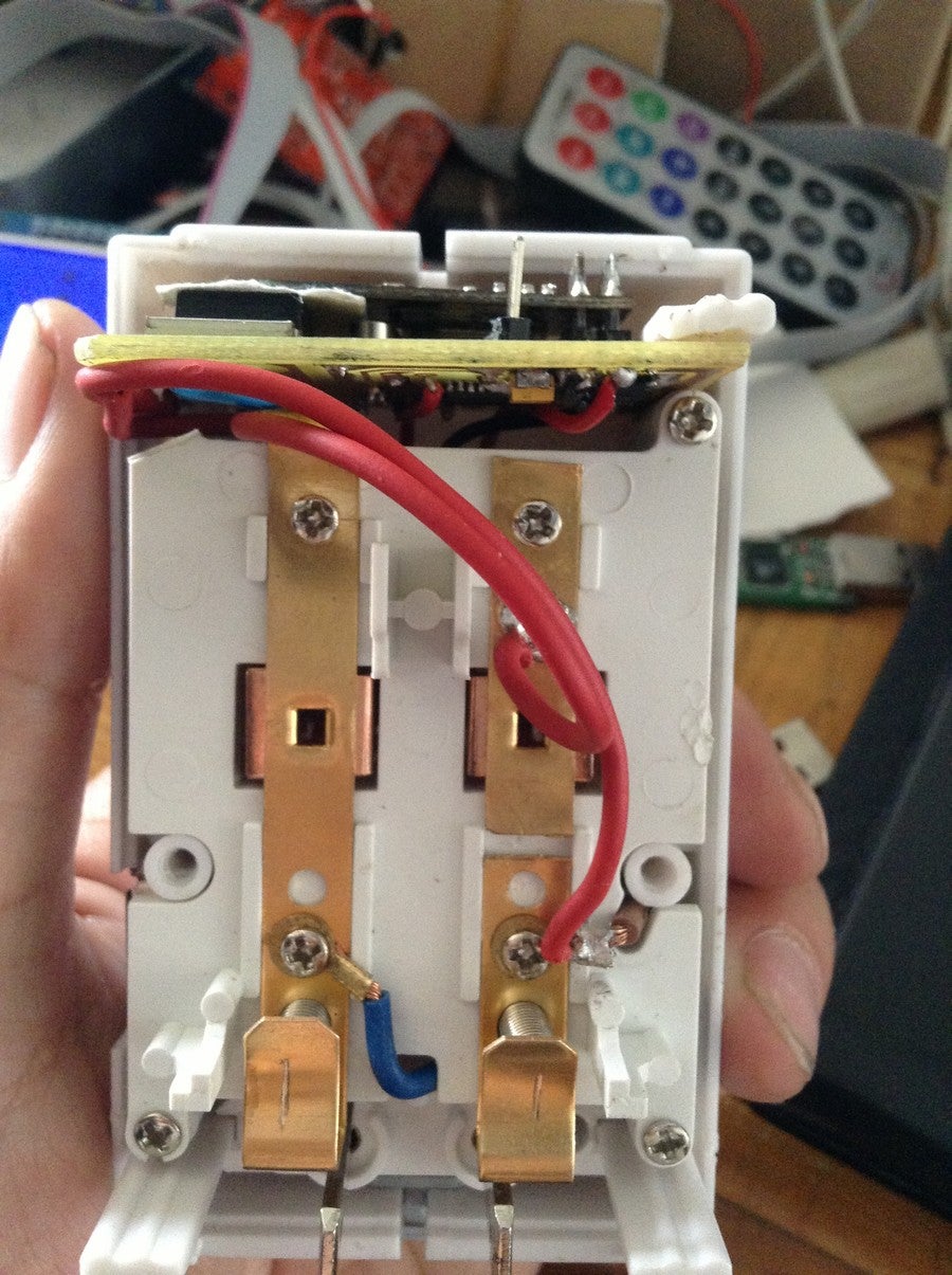
Step 3: [hardware Solution 1.3] Socket DIY
![[hardware Solution 1.3] Socket DIY](https://content.instructables.com/F34/ZXPE/HK6XBE9C/F34ZXPEHK6XBE9C.jpg?auto=webp&fit=bounds&frame=1&height=1024auto=webp&frame=1&height=300)
Hardware solution 1.3
in solution 1, I build one network gate board (a master node) and one network node board (a slave node), PCB open source files of the boards are provided for your reference. A socket DIY is required if you want to pack a network node into it.
- custom designed network gate (master)
- custom designed single network node (slave)
- DIY a socket
============
- rewire power supply net in the socket and connect it with slave node board, so that it canbe controlled by instructs from network gate (master node)
Step 4: [hardware Solution 2.1] Build Network Gate (master) Board
this step is same as [Hardware solution 1.1]
Step 5: [hardware Solution 2.2] Build Multiple Channels Network Node (slave) Board
![[hardware Solution 2.2] Build Multiple Channels Network Node (slave) Board](https://content.instructables.com/FAJ/HW4W/HKEWQWFZ/FAJHW4WHKEWQWFZ.png?auto=webp&fit=bounds&frame=1auto=webp&frame=1&height=300)
Hardware solution 2.2
in solution 2, I build one network gate board (a master node) and one multiple-channel network node board (a slave node)
- custom designed network gate (master) (same as 1.1)
- custom designed multiple-channel network node (slave)
- DIY a socket (same as 1.3)
==================
- designed a 4 channel switch board (slave node)
Step 6: [hardware Solution 3.1] Build Network Gate (master) Board With Microduino
![[hardware Solution 3.1] Build Network Gate (master) Board With Microduino](https://content.instructables.com/FLH/2ZF3/HKEWQWKH/FLH2ZF3HKEWQWKH.jpg?auto=webp&fit=bounds&frame=1&width=1024auto=webp&frame=1&height=300)
![[hardware Solution 3.1] Build Network Gate (master) Board With Microduino](https://content.instructables.com/FS0/GU5Y/HKEWQWKE/FS0GU5YHKEWQWKE.jpg?auto=webp&fit=bounds&frame=1&width=1024auto=webp&frame=1&height=300)
![[hardware Solution 3.1] Build Network Gate (master) Board With Microduino](https://content.instructables.com/F6W/0TDU/HKEWQWKI/F6W0TDUHKEWQWKI.jpg?auto=webp&fit=bounds&frame=1&width=1024auto=webp&frame=1&height=300)
![[hardware Solution 3.1] Build Network Gate (master) Board With Microduino](https://content.instructables.com/F6T/FNNJ/HKEWQWKL/F6TFNNJHKEWQWKL.jpg?auto=webp&fit=bounds&frame=1&width=1024auto=webp&frame=1&height=300)
![[hardware Solution 3.1] Build Network Gate (master) Board With Microduino](https://content.instructables.com/FZ3/A1ZJ/HKEWQWKM/FZ3A1ZJHKEWQWKM.jpg?auto=webp&fit=bounds&frame=1&width=1024auto=webp&frame=1&height=300)
![[hardware Solution 3.1] Build Network Gate (master) Board With Microduino](https://content.instructables.com/FA4/RMKU/HKEWQWKD/FA4RMKUHKEWQWKD.png?auto=webp&fit=bounds&frame=1auto=webp&frame=1&height=300)
![[hardware Solution 3.1] Build Network Gate (master) Board With Microduino](https://content.instructables.com/FT8/Q1T8/HKEWQWI8/FT8Q1T8HKEWQWI8.jpg?auto=webp&fit=bounds&frame=1&height=1024&width=1024auto=webp&frame=1&height=300)
![[hardware Solution 3.1] Build Network Gate (master) Board With Microduino](https://content.instructables.com/FCR/JY69/HKEWQWI9/FCRJY69HKEWQWI9.jpg?auto=webp&fit=bounds&frame=1&height=1024&width=1024auto=webp&frame=1&height=300)
![[hardware Solution 3.1] Build Network Gate (master) Board With Microduino](https://content.instructables.com/FG1/2VDW/HKEWQWIC/FG12VDWHKEWQWIC.jpg?auto=webp&fit=bounds&frame=1&height=1024&width=1024auto=webp&frame=1&height=300)
![[hardware Solution 3.1] Build Network Gate (master) Board With Microduino](https://content.instructables.com/FS1/PWOV/HKEWQWID/FS1PWOVHKEWQWID.jpg?auto=webp&fit=bounds&frame=1&height=1024&width=1024auto=webp&frame=1&height=300)
Hardware solution 3 Network Gate with Microduinos + Custom designed network node
=============================
Solution3.1 build a etwork gate (master) with Microduinos
1. Check Microduino information at http://wiki.makermodule.com , a small Arduino compatible board, it’s easier for newbies.
Microduino provide MEGA644,28J60,24L01,OLED modules, just stacking the Microduino boards together and connecting an infrared receiving head into the board, the system works.
2. I used Microduino-Core+, Microduino-FT232R, Microduino-ENC28J60 + Microduino-RJ45,Microduino-nRF24,Microduino-OLED in “roomduino”, a Test-Microduino extension board is also used for better experience to upload program.
3. The last step is solder an IR receiver to the boards and connect Microduino-OLED through IIC interface.
Step 7: Roomduino Software Solution

network configuration:
1. Set router network gate as 192.168.1.1
2. set Master node IP address as below: it should match the net mask of router:
static byte myip[] =
{
192, 168, 1, 121
};
static byte gwip[] =
{
192, 168, 1, 1
};
static byte dnsip[] =
{
192, 168, 1, 1
};
3. Properly set YEELINK.com ID:
urlBuf0[] is YEELINK switch address, the other four are for slave node
4. fill your YEELINK API Key in the last line.
char website[] PROGMEM = "api.yeelink.net";
char urlBuf0[] PROGMEM = "/v1.0/device/xxx/sensor/xxx/";
char urlBuf1[] PROGMEM = "/v1.0/device/xxx/sensor/xxx/";
char urlBuf2[] PROGMEM = "/v1.0/device/xxx/sensor/xxx/";
char urlBuf3[] PROGMEM = "/v1.0/device/xxx/sensor/xxx/";
char urlBuf4[] PROGMEM = "/v1.0/device/xxx/sensor/xxx/";
char apiKey[] PROGMEM = "U-ApiKey: xxx";
Step 8: Open Source and Contact Information

source code: https://github.com/wasdpkj/Roomduino
Author: wasdpkj@hotmail.com
https://www.facebook.com/Microduino

Participated in the
Arduino Contest

Participated in the
Remote Control Contest

Participated in the
Weekend Projects Contest

![Tim's Mechanical Spider Leg [LU9685-20CU]](https://content.instructables.com/FFB/5R4I/LVKZ6G6R/FFB5R4ILVKZ6G6R.png?auto=webp&crop=1.2%3A1&frame=1&width=306)


