

Introduction: Arduino Class: Skills Infusion & Going Further


Arduino Class Table of Contents:
In this lesson, we'll cover a few important concepts you'll need to understand to create your own Arduino projects. We'll get up to speed on soldering, code libraries, addressable LEDs, organizing code with functions, and calculating the power requirements of your projects.
Step 1: Supplies
To follow along with this lesson you will need:
- Soldering iron and solder
- 1 meter of 60/m RGBW NeoPixel strip (or other WS2812b RGBW LED strip)
- Breadboard wires
- Small needlenose pliers
- Flush diagonal cutters
- Wire strippers
- Multimeter (optional but very handy)
- Tweezers
- Third hand tool
- Desoldering braid or solder sucker
- Small pushbutton
- Arduino Uno board and solderless breadboard on a mounting plate
- USB A-B cable
Step 2: Soldering

Soldering is an extremely useful electronics construction technique, and it's surprisingly satisfying to do. It does take practice to excel, like most worthwhile endeavors, so take a moment to set your intention for this lesson. Establish a goal to keep trying even if you become frustrated, and be kind to yourself during the process. And wear eye protection— nobody wants hot bits of metal in their eyes! While we're talking safety, work in a ventilated area and wash your hands afterwards, especially before touching any food. Be cautious and alert around your soldering iron; keep burnable things away from the hot part (including your skin), and turn it off (or unplug it) rather than leave it unattended.
We'll use soldering to attach wires onto a piece of NeoPixel strip, so we can plug it into the solderless breadboard. A basic soldering iron like the one recommended for this class will take you quite far, and if you do upgrade to a temperature-adjustable soldering station like mine, you can keep your basic iron as a spare or give it to a friend. Plug it in, turn it on, and let it heat up for a few minutes (mine is set to 650 degrees F). Keep a damp sponge or brass sponge nearby (many soldering iron stands come with a small sponge). When the iron is hot, clean the tip with a few wipes across the sponge or stabs into the brass coil sponge. Then touch the iron to your solder for a moment to transfer a little bit of solder to the tip, called tinning the soldering iron. Repeat this cleaning and tinning procedure regularly while using the soldering iron to prevent buildup of excess solder and oxidation.
Soldering works by heating up the metal components to be joined, then allowing low temperature alloy solder to melt and flow and harden between them. Solder is not glue. If you melt solder onto the tip and then smear it around the component leads, you will not create a good electrical connection.
Solder is used with flux (usually built right into the solder, labeled "rosin core"), which is a substance that helps delay oxidation. It shields the immediate area of the bonding metals, and boils/burns away as they cool. Solder fumes are mainly tree sap, which flux is made from. If you apply molten solder to cold components, it could potentially look soldered, but a layer of oxidation is hidden inside, created when the solder suddenly cooled as it touched the base component. This is called a cold solder, which prevents electrons from flowing across the solder joint. Always heat your components fully before applying additional solder! Good solder joints will look smooth and shiny, not blobby or dull.

A third hand tool helps immensely when it comes to stabilizing your work, especially as you're learning to hold the iron steady. I tend to avoid caffeine around workshop time, too. I like to put a little bit of heat shrink tubing over the jaws of my third hand tool, to soften its bite.


Prep three of your breadboard wires by cutting off the connectors at one end and stripping the ends to expose the bare strands of wire. Twist the strands of each wire to keep them together, then heat up the wire with your soldering iron and apply a small amount of solder. Remove the solder before removing the iron, to give the molten solder one last moment to settle in. Repeat to tin your other two wires, then set them aside.


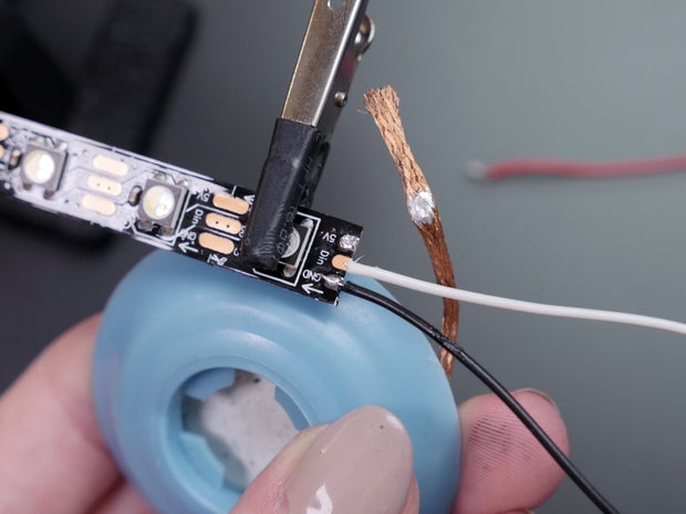
Cut a piece of your NeoPixel strip 19 pixels long, using your flush diagonal cutters to clip straight across the middle of the copper pads. Remove it from the silicone sheathing and identify the input— the arrow markings on the strip point away from it. Clip the input end it into your third hand tool with the back of the strip facing you. Tin the center copper pad by touching your soldering iron to it, then applying a small amount of solder. Move your tip around the copper pad to spread the bead of solder around.


Now that your two components are tinned, it will be easier to solder them together. Pick up your white wire in one hand and your soldering iron in the other. Hold the tinned wire end to the tinned copper pad, and reheat the two components at the same time. The solder on each should flow together, if it doesn't, you may need to apply some more. Remove your iron before letting go of the wire, so the solder has a chance to cool, securing the wire in place. If you find it difficult or too hot to hold the wire with your fingers, use a pair of tweezers or pliers.


Flip over your NeoPixel strip and similarly tin and solder wires to the other two copper pads (red wire for 5V, black wire for GND). It doesn't really matter which side of the copper pad you solder to, but alternating sides gives your solder joints a little more elbow room. Trim any excess wire protruding from the copper pad. Now you're ready to plug the strip into your breadboard and get the LEDs glowing (we'll do that next)!

If you make a mistake, apply too much solder, or just want to disassemble your work, you can desolder the joint by simply reheating it and pulling the wire away. For more entangled components, you can use copper desoldering braid to remove excess solder (its highly interleaved surface area draws the solder in with capillary action), or a suction desoldering pump.
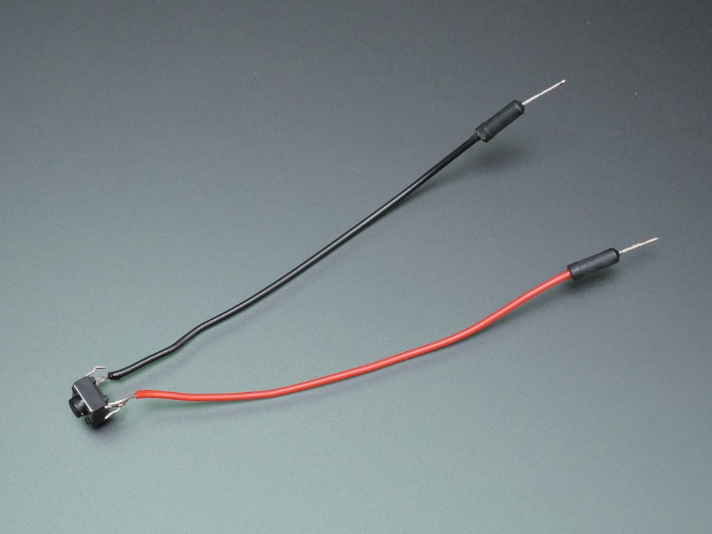
Practice your soldering skills again by attaching wires to two diagonal leads of a pushbutton. Tin the wires and the pushbutton leads, then reheat them to allow the solder to flow. Set this pushbutton aside for the final project.
Step 3: Addressable LEDs and Code Libraries
Now that the strip is soldered, we'll need to program the Arduino to turn the LEDs on. NeoPixel is the Adafruit brand name for WS2812 addressable "smart" LED strip (as opposed to analog LED strip). Each pixel has a chip inside to communicate with the Arduino board and other pixels on its strip (it can't light up without a controller). To control the strip, some additional Arduino functions are required, and we can get them by installing the code library. Arduino code libraries empower you to leverage powerful computing tools using simple commands. Arduino recognizes these add-on modules and then you can use their commands within your program. Arduino libraries exist for all sorts of complex tasks, like controlling large LED panels, reading sensors, creating sounds, and many more.

In your Arduino software, navigate to Sketch -> Include Library -> Manage Libraries...

When the Library Manager opens, search for "NeoPixel" in the upper right field. Optionally select a version of the library from the dropdown menu, and click the "Install" button. Now you're all set to use the NeoPixel library in your Arduino sketches! You can use the library manager to install all kinds of fun extensions to the Arduino programming language that help you interface with sensors, motors, and more.


Take a close look at your pixel strip. Each pixel contains a very small RGB LED, which can theoretically create any color of light. However, generating pure white poses a challenge for RGB LEDs and often leaves users disappointed in the tinted or poorly mixed quality of light produced. For this reason, the RGBW strip includes a white LED inside its package as well.

Coding for these pixels will include four brightness values to describe a pixel color: red, green, blue, and white. This is similar to analogWrite(); in the RGB LED example from your first exercises: you provide a number from 0-255 to represent the brightness of the LED. The functions in the NeoPixel library take pixel numbers and these color values as arguments, then translate them into the commands to send along the LED strip.
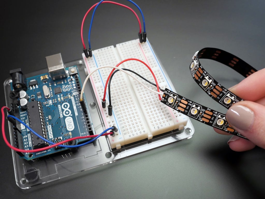
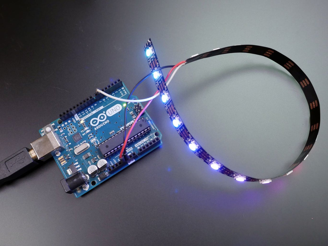
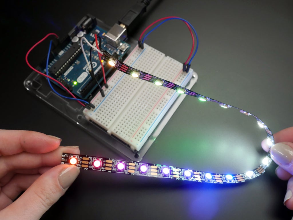
Now that our NeoPixel strip has wires attached to it, let's connect it to the breadboard. The 5V wire (red) goes to your breadboard's power bus, and the ground wire (black) goes to the breadboard's ground bus. Connect the data wire (white) to Arduino pin 6.
Find this circuit on Tinkercad
Download/copy the code from the Tinkercad Circuits module (Code button->download code button) and open it in your Arduino software. Plug in your USB cable and upload to your Arduino Uno, and watch the pixels light up and change colors.
Let's take a look at the Arduino sketch:
#include <Adafruit_NeoPixel.h>

#define PIN 6

#define NUM_LEDS 19

#define BRIGHTNESS 50

// Parameter 1 = number of pixels in strip
// Parameter 2 = pin number (most are valid)
// Parameter 3 = pixel type flags, add together as needed:
//   NEO_RGB     Pixels are wired for RGB bitstream
//   NEO_GRB     Pixels are wired for GRB bitstream, correct if colors are swapped upon testing
//   NEO_RGBW    Pixels are wired for RGBW bitstream
//   NEO_KHZ400  400 KHz bitstream (e.g. FLORA pixels)
//   NEO_KHZ800  800 KHz bitstream (e.g. High Density LED strip), correct for neopixel stick
Adafruit_NeoPixel strip = Adafruit_NeoPixel(NUM_LEDS, PIN, NEO_GRBW + NEO_KHZ800);
The first section instantiates the NeoPixel strip and sets up the configurable bits of the program like the pins connected to the NeoPixel strip and button, the number of pixels, and global brightness level. #define statements are similar to variable declarations, but are used for information that does not change while the program is running. They take up less memory than regular variable declarations.
void setup() {

  strip.setBrightness(BRIGHTNESS);
  strip.begin();
  strip.show(); // Initialize all pixels to 'off'
}
strip.show(); is used any time you want the pixels to change. Setting the pixel colors and showing the latest changes are broken up into two separate commands.
void loop() {
  // Some example procedures showing how to display to the pixels:
  colorWipe(strip.Color(255, 0, 0), 50); // Red
  colorWipe(strip.Color(0, 255, 0), 50); // Green
  colorWipe(strip.Color(0, 0, 255), 50); // Blue
  colorWipe(strip.Color(0, 0, 0, 255), 50); // White

  whiteOverRainbow(20,75,5);

  pulseWhite(5);

  // fullWhite();
  // delay(2000);

  rainbowFade2White(3,3,1);
}
The main loop just calls other functions. Let's take a closer look at colorWipe();, defined just below the main loop, and takes two arguments: a color (strip.Color(r, g, b, w)), and a speed value.
// Fill the dots one after the other with a color
void colorWipe(uint32_t c, uint8_t wait) {
  for(uint16_t i=0; i < strip.numPixels(); i++) {
    strip.setPixelColor(i, c);
    strip.show();
    delay(wait);
  }
}
The function definition starts with what type of data the function will return, or send back to the main program. In this case the function returns nothing, so the word void is used at the start of the definition. Next is the name of the function, which is up to you. Then in parentheses are the arguments the function takes, in this case a 32 bit unsigned integer called "c" and an 8 bit unsigned integer called "wait." Inside the function, these local variables are used to reference the information you passed to it from the main loop (or from another function). The function itself steps through all the pixels in the strip (using a for loop and a NeoPixel function called strip.numPixels();), coloring and showing each one before moving to the next. The other functions in the RGBW strandtest program work the same way, and use clever color math to achieve stunning light patterns.
Step 4: Write Your Own Functions
You can easily modify colorWipe(); to start coding up your own unique animation. Try copying the whole function definition, and change the name of the function (or copy and paste this snippet just after the closing curly brace of your main loop).
// my first NeoPixel animation
void animationExperiment(uint32_t c, uint8_t wait) {
  for(uint16_t i=0; i < strip.numPixels(); i++) {
    strip.setPixelColor(i, c);
    strip.show();
    delay(wait);
  }
}
Then start playing around with the code. Say I want to light up a random pixel in the strip instead of lighting them up in order. I could use Arduino's built-in random(); function to pick a pixel, which generates a random number between the two arguments:
strip.setPixelColor(random(0,strip.numPixels()), c);
Call your new function inside your main loop:
void loop() {
  animationExperiment(strip.Color(255, 0, 0), 50); // Red
}
Repeatedly upload your code experimentation to your Arduino Uno board, making small changes each time. If you find an effect you like, stop editing that function and create a new one, either by copying/pasting a function and changing its name, or typing out the definition:
void functionName() {
  //contents
}
Congrats, that's all there is to creating functions in Arduino! They're a handy tool to separate out a chunk of code you want to access repeatedly, and make your code easier to read.
Step 5: Planning for Power

As we touched on in the DC motor and NeoPixel circuits, it's likely you'll want to power your Arduino project with something other than your USB cable. Whether you're building an LED sign that plugs into the wall, or a battery-powered GPS circuit for your next geocaching adventure, just a bit of simple math will help you pick the right power supply every time. All you do is add up the current draw of each component, and pick a supply that matches or exceeds your amperage needs. Components list their current draw on product pages and datasheets. For example, 10 LEDs that each draw ~20mA, when hooked up to an Arduino board that draws ~50mA. 10*20+50 = 250mA. A 250mAh battery will run this circuit for one hour. The rechargeable AA pack in the picture above provides 1900mAh, so it can power the circuit for 1900mAh/250mA = 7.6 hours. When hooking batteries up in series, their voltage adds up but their amperage does not (4 AA batteries is 4x1.5V but not 4x1900mAh).
In reality your circuit may use far less power than the calculated maximum. LEDs that are dimmed with PWM only use a fraction of the power of those at full brightness, for example. Having more current available than you need isn't a bad thing, as it helps prevent overtaxing your supply. Circuits only draw as much power as they need!
For most Arduino projects, a 4xAA or 3xAAA pack will suffice. You can connect directly to the Arduino's 2.1mm barrel jack with a battery pack or wall supply, or plug the USB cable into a wall adapter. Many smaller Arduino compatible boards have JST ports on board, a common connector for lipoly batteries. Some even have USB charging right on the board! Lipoly batteries have special safety concerns, so be sure not to short circuit or abuse them, store them at extreme temperatures, and read any manufacturers' safety warnings before working with them.
Step 6: Learning to Fish

You've made it to the end! What follows are some parting words of advice for venturing off into the world of Arduino on your own.
Rest assured that because of its rich community history, most of your early questions about Arduino are already well documented online in tutorials and forums all over the web. However you are just learning the vocabulary by which to access this vast catalog of resources, and things may be a little rocky at first. Remind yourself there is a learning curve, and everything will get easier and come more naturally after some time and repeated practice. Here are some tips to improve the results of your self-directed learning.
Google with gusto - Get good at search engines! Use quotes to search for Arduino error messages, brainstorm key words around your idea and look for folks who've documented similar projects before. This can be handy during the parts brainstorming step but also for learning more uses for the parts you already have. Become a regular lurker in the Arduino and Adafruit forums, where most beginner roadblocks are solved many times over. Say it with me: "I bet I can find someone online who's had this question before; I just have to find it."
Sharing (code) is caring - Arduino is built on open source ideas. Innovation flourishes when technology is shared! You'll find countless libraries, code examples, Github repositories, and more resources to aid in your coding education. It behooves you to read up on the history of open source, learn about licenses commonly used for code and hardware, and credit your sources when building on others' designs.
Document your process - It's easy to forget to photograph your circuit before revising it when you're in the throws of frustration over a bug. Set a timer to remind yourself to take pictures and video while building! You may find yourself wanting to look back at previous iterations to avoid making the same mistakes twice. Additionally, you'll find a supportive community of makers willing to help you along your way if you choose to share your projects online in forums, your own website, or here on Instructables. Documenting your struggles along with your successes will connect you with knowledgeable folks around the globe, and maybe even help someone else who's just learning Arduino.
Step 7: Durability & Weatherproofing
It's quite likely you want to create Arduino projects that will function for some time while enduring repeated movement or exposure to the elements. Designing durability into a circuit requires some forethought of potential failure modes, often only discovered through repeated prototyping and improvement upon prior failure. Here are some tips on design and construction for durability. Remember to read and follow manufacturers' instructions and safety procedures when using any hazardous materials.
Protect the power supply - The most important part of your circuit to keep safe is the battery and power connections. A short circuit here could trip a circuit breaker, permanently damage components, or cause a fire.
Strain relief - Remember that your circuit has both mechanical and electrical connections. Sometimes they are one in the same, like the Arduino's USB and power ports. However it's always a great idea to add mechanical connections to your projects to prevent wires from tugging on their solder joints. You can use zip ties to secure wires, and most circuit boards have mounting holes for use with screws or hand sewing. For connections that will bend repeatedly, use stranded wire instead of solid-core.
Know your adhesives - Using the right glue for the job is critical for your circuit's durability! For instance, few things will actually stick to the silicone sheathing that comes around LED strip. Only certain silicone adhesives will provide a weatherproof seal in this case. Permatex 66B is my favorite for NeoPixel strip's silicone sheathing. Any adhesive should be tested to check that it bonds to both surfaces. Hot melt glue was convenient for the infinity mirror project in this class, but it stinks for durability. Instead I highly recommend E6000 craft adhesive, or its cousin Quick Hold. These take longer to dry but stick to everything (except silicone) and dry clear and flexible. To learn more about adhesives, check out our Glue class!
Humidity & moisture - It's important to protect your circuit from water, which will cause shorts. If you're thinking of making an electronic costume, for instance, did you consider that your evaporating sweat could be a factor? Where will your circuit be located and what humidity/water conditions can you expect there? Generally you can think of using coverings and coatings to address this issue. You can find completely waterproof enclosures for your projects, cover your circuit with waterproof fabric, and use waterproof adhesives to seal up any openings. I often use clear nail polish to protect bare components on costumes/wearables. Clear spray paint is also a good option, however I'm not a big fan of the new hydrophobic coatings like NeverWet. They were designed for things like the circuit board inside your phone, and don't function well outside that context because of their extreme physical fragility, sensitivity to sunlight, and highly toxic nature.
However water is not a circuit's nemesis! If the battery/power supply is removed, most circuits won't be damaged by water, so long as they dry out before being plugged back in (and weren't left a long time to corrode). Exceptions exist for components that water can get inside, like microphones. But generally, it's ok to hand wash your Arduino projects after unplugging the power and removing any batteries.
UV and temperature fluctuation exposure - Over time, many plastics, adhesives, and other protective materials break down when exposed to sunlight. Wire sheathings may become brittle and crack open. Coatings may break down and fail. Think about the temperatures your circuit is likely to experience, too. Most batteries' lives are shortened by exposure to high or low temperatures, for instance. Check the datasheets for your components to learn their operating temperature ranges.
This is just the tip of the durability iceberg, folks. There are whole fields of study devoted to the topic, in mechanical engineering, industrial design, and materials science just to name a few. However for most projects, a bit of E6000 and some zip ties really go a long way towards keeping your projects alive.
Step 8: Next, Try...

If you completed all the lessons in this class, you're now ready to take on countless Arduino projects, including your own designs. Don't know where to start? Try my Easy Infinity Mirror with Arduino Gemma. You may also find many of the early code examples to be great starting points when building your own sketches. For your next class, consider Internet of Things, Electronics, Wearable Electronics, or Robots, which will all deepen your understanding of some of the concepts from this class.
Here are some projects from the Instructables community to help inspire your next creation:

Word Clock by drj113

Secret Knock Detecting Door Lock by Grathio

HC-SR04 Distance Sensor by jsvester

Instagram Inspired DIY Photo-Booth by alexandermorris

Self-Watering Plant by randofo

Existential Emergency Phone by randofo
Have you made a project with Arduino you'd like to share? Please consider writing an Instructable about it, and enter it in one of our frequent contests.
Thank you so much for taking my Arduino class! If you enjoyed your experience, consider sharing it with a friend. And I'd like to receive your feedback either way, so I can improve this class!
Arduino Class Table of Contents:


