

Introduction: The HacqueBoard


The Protopalette is a commercially available prototyping workbench for the Arduino and similar microcontrollers. Unfortunately, there exists no similar tool for the more powerful credit card sized computers, the ones that are capable of running a full-fledged operating system. Well, there wasn't one until now. Herewith, I present . . . (ta da) . . . the HacqueBoard*.
Using as a base a large bamboo kitchen cutting board, we will assemble a versatile prototyping system/testbed that provides, among other resources, a miniature HDMI display screen, a 3.3v 1A power supply, a socket and I/O module with colored LEDs and a piezo buzzer, solderless breadboards, and even a Hackduino for low-level control of sensors and peripherals. There will be an elevated wooden platform in the lower left corner for fastening, by screws, interchangeable CPU boards, such as the Raspberry Pi or PCDuino. This will be a simplified all-in-one solution for prototyping, designing, or even just playing around.
* Note that HacqueBoard is not a trademark. I herewith grant this name/designation to the Public Domain, and all you hacquers out there will be able to use it freely without fear of legal repercussions.
Step 1: What You Need


Parts and Components
- Large bamboo cutting board
- Cheap miniature (7") HDMI display, about $30 on eBay
- A 3.3v miniature Arduino-compatible board or a Hackduino (optional)
- An Arduino Pro Mini (optional)
- Spring-action cabinet hinge
- 2 blocks of pine wood, approx. 2" x 4" x 1/2" ea.
- Several disc magnets
- 4 rubber washers, flat disc type
- A small stripboard
- A couple of small/medium solderless breadboards
- A USB hub (optional)
- Keyboard with integrated trackpad or trackball, USB or wireless
- About a dozen assorted wood screws
- A handful of different colored LEDs (preferably the super-bright variety)
- A couple of male and female single-row header strips
- A couple of female double-row female header strips
- 1 closed-pin jumper cap
- A piezo buzzer
- 3.3v regulator
- 1 - 1N4001 diode
- Capacitors: 100uF (1 ea. 25v and 10v ratings), and 2x .01 uF disc caps
- Resistors: 4x 1k
- A liberal supply of wire jumpers (for breadboarding)
- 5v, 3A power supplies, 2x
- 1x HDMI cable
- 1 polyfuse
- Solder
- Glue: both carpenter's wood glue and contact cement
Tools
- Power drill
- Rotary tool
- Soldering iron
- Hot-melt glue gun
- Screwdriver
- Shear cutter
- Needle-nose pliers
- A spring clamp
Total cost might be held to $75 or so with some judicious shopping and use of parts on hand.
Step 2: The I/O Module


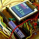
Our HacqueBoard features a versatile I/O (input/output) module, containing socket rows, multiple LEDs, a piezo buzzer, and a 3.3 volt, 1-amp power supply. This will facilitate attaching components, peripherals, and various sensors to the CPU board, using jumpers.
The socket section of the board includes two double rows of female headers, spaced for plugging in an Arduino Pro Mini (3.3v) module. There are also double rows of sockets for other purposes. Note that vertically adjacent pins on the double rows are connected on the solder side of the board, so that a jumper wire next to a component pin is in electrical contact with that pin (see the pictorial). We used a rotary tool with a burr head to cut across traces on the solder side of the board.
At the lower side of the I/O module is a 3.3v power supply (see schematic and pix). Of course we could have purchased a ready-made 3.3v supply, but since this is an Instructable, rather than a "Purchaseable," we prefer to build it ourself, from scratch.
And then we have an assortment of colored LEDs and a piezo buzzer in the center of the board. Each LED has a 1K ohm current-limiting resistor connecting to the ground buss and a female-header socket for hookup. The buzzer has a 49 ohm current-limiting resistor and its own socket. Some of these components, particularly the header sockets, are fragile, so we have "potted" them in hot-melt glue. This makes the I/O module less esthetically pleasing, perhaps, but much more robust.
Let's test the board by supplying power to the power input jack, then jumpering the LEDs to the Vcc buss. Do they light up? Good. Now, try jumpering the piezo buzzer to Vcc. Ouch, that's loud!
Step 3: Mounting the Display Screen


The first module we will mount on our base board -- the bamboo cutting board -- is the nifty $30 7" HDMI display screen purchased on eBay. The upper right-hand corner is a convenient spot for the screen, and the driver board will mount directly below, connected by a ribbon cable. This will permit a comfortable sight-line to the display, once we figure out how to provide a proper viewing angle, in a later step.
As it happens, this particular model display has a metal back, which allows us to mount it by means of a couple of flat disc magnets. The magnets, fortunately, will not interfere with the electrical characteristics of the display. If you should happen to have a display type without a metal back, there is an alternative mounting method we will discuss later in this step. Utility or contact cement securely glues the magnet to the base board, within the markings we penciled in for the position of the display.
When the glue under the magnets has dried, we can position the display panel atop the magnets and gently move it around to the correct position (penciled in beforehand). Next, we need to connect the ribbon cable from the display to the appropriate port on the driver board. The port has a small tab that needs to be pulled open. Careful! This is a delicate operation. Now, carefully insert the ribbon cable from the display into the port, with the shiny row of contacts facing upward (see picture). It will only go in a few millimeters. Finally, push the tab back inward to lock the cable.
Gently stretch the cable flat, to position the driver board below the display. We will affix the driver board with wood screws through the mounting holes to the bamboo base board. Likewise, the small control panel, connected to the driver board with a ribbed ribbon cable, attaches to the base board with screws.
* * *
Yes, but what about those displays that lack a metal backing? Magnets are not useful for attaching these babies. Fortunately, there is an alternative strategy for this type of display. We use flat rubber washers, of the type sold in the plumbing department of hardware stores for fixing leaky faucets. We can screw those to the base board, at the side of the display panel, so that the washers overlap the edges of the panel. The gentle pressure of the rubber holds the panel in place on both the left and right. And, the washers conveniently have a hole in their center for the screws. To hold the bottom of the panel, we can use small metal picture hooks. A couple of these prevent the panel from slipping down. Refer to the last couple of pictures, above.
Step 4: The CPU Board Mounting Platform


We need a way to mount processor boards on the base board. First we experimented with using a spring clamp to hold the processor board to the base board. This is easy and lends itself to quick change of processor boards, but it risks cracking or otherwise damaging delicate electronics on the board. Definitely not recommended!
A better way is to use a block of wood as a mount. A block of 2" x 4" x 1/2" pinewood provides a platform that will accommodate most varieties and sizes of the common Raspberry Pi type boards. This we will locate on the lower left-hand corner of the base board. This makes it convenient to connect an HDMI cable to the display board, as well as providing ready access to the other connectors and ports on the processor board.
Clamp the processor board mounting block in its location. Then drill all the way through the block and about halfway into the base board, using something like a 1/8" drill bit. Now, we can easily screw in the flat-head wood screws that will hold the block in place. Screw them in flush, or even a bit below the surface of the wood. Because pine wood is so soft, it's probably not necessary to countersink the screws. In any case, we will use a thin cardboard underlay to insulate the underside of the processor board from accidental contact with the exposed screw heads (see photo).
A typical processor board has a set of screw holes intended for small machine screws. However, small wood screws will also fit into these holes, and this makes it possible to fasten virtually any CPU board to the wooden "platform." If necessary, the wood-block platform can itself be easily replaced, if there are too many screw holes in it after multiple processor board interchanges.
Step 5: The Rest of the Modules


It's time to add the other modules to our baseboard. We have all that free real estate, and it would be a shame not to use it!
In the upper left-hand corner, there's room for a 3.3 volt Arduino board, or a custom-built Hackduino. Running at 3.3 volts, it eliminates the need for level shifters when interfacing to the main processor board. We can mount the Hackduino with screws, or, if necessary, using the rubber grommet method discussed in an earlier step.
Below the display panel and its driver board, there's just enough room for a mini solderless breadboard. And, in the lower right-hand corner of the base board we can emplace a medium-sized solderless breadboard. Both of these mount securely by exposing the adhesive layer underneath and pressing them down firmly in place. I had positioned another mini breadboard to the left of the medium-sized one, but, as it turned out, it blocked access to the display driver board's HDMI jack. This breadboard had to be removed. Live and learn.
Shown in the picture above is a small blue USB hub plugged into the processor board. I had briefly considered permanently mounting it on the base board, but room was getting a bit tight, and anyhow not having it mounted gave more flexibility, since some processor boards did not require an additional hub.
Well, we're almost done, except for a couple of little details.
Step 6: The Gimmick


Our project is almost complete, but there's still a problem. If the base board lies flat, then the viewing angle on the display screen is awkward. What to do? Well, it just happens that I had a spring-action cabinet hinge in my junk box, and, as they say, the rest is history.
Let us take two 2" x 4" x 1/2" pine wood blocks, and screw/glue them together, offset by 2" (see picture). This will give us a long enough prop to angle the base board up to a comfortable viewing angle. But, just in case, we'll add two long wood screws, screwed into the narrow end edge of our two-block gimmick (see picture). Now, we attach the prop to the cabinet hinge, using more wood screws. Fine and good, but how will the gimmick attach to the base board?
On the top, the display screen end of the base board, we drill two holes, spaced to fit the unused mounting holes on the hinge. Now, we can screw-mount our contraption onto the base board in such a way that it will "snap" down to prop up the board. A bit of experimentation may be in order, to get it just right. Do you have a comfortable viewing angle now? Great! Then, we're ready to go on to setup and testing.
Step 7: Setup and Testing


The setup of our HacqueBoard involves connecting up all the cables, power supplies, and necessary peripherals.
Hook the processor board to the display driver board with a male-male HDMI cable. Hook up a keyboard and mouse (or a keyboard with integrated trackball or trackpad) to the processor board. And, oh yes, the processor board has to have an operating system, usually some flavor of Linux or Android, loaded into either on-board flash memory or into a micro-SD card.
We need to connect at least two power supplies: one for the processor board and one for the display board. The particular display board we used take a coax power connector at 5 - 12 volts, 1/2 amp. The processor boards generally require 5v at 2A, and with a micro-USB cable connection, but this varies.
With everything else in place, apply power to the display board (it should light up) and then to the processor board. Wait a few seconds and pray. Watch the display panel. Is the operating system booting up? If so, then congratulations!
Step 8: Summing Up

Now that we have a working HacqueBoard, we can use it for rapid prototyping. Much of what we need is right on the board, and all we need to do is connect cables, peripherals, and jumpers. The solderless breadboards let up plug in sensors and other components. The on-board Hackduino enables interfacing to the Arduino ecosystem. And, it's all possible for less than $100 in parts cost.
Note that you need not follow the layout of modules detailed in this Instructable. You may delete anything you don't need, and add components to fit your purpose. Customize, customize!
What's next? Perhaps a crowd-funding campaign to raise money to mass produce these babies and sell them for profit. Well, folks, I will not be the one to do it. I'm open sourcing this project so that some entrepreneur out there can make them and sell them, if she likes.
Step 9: Afterword: an Alternative Method of Mounting the Processor Board


Those who dislike mounting the processor board with wood screws might consider using magnets. First, affix two or more metal strips, or "rails," in parallel on the lower left-hand corner of the HacqueBoard. Use wood screws for this. Then, insert three or more small machine screws through the mounting holes of the processor board. The nuts, on the solder side of the board, have small niobium disc magnets adhering to them by magnetic force. Be very, very careful not to short out any live leads on either side of the board! The disc magnets will cling to the metal strips. If necessary, glue the magnets to the underside of the nuts, though this is a drastic measure.
It's possible to substitute adhesive magnetic tape strips, or even long/thin bar magnets, for the metal strips. Note that a couple of small washers or an extra nut atop the screw, on the component side of the board can help get the proper height and spacing.
Carefully position the processor board atop the metal or magnetic tape strips. The magnets permit it to be moved around a bit. Magnetic force is quite sufficient to hold the board in place, though a bit of care is necessary when plugging cables into it.
Participated in the
Raspberry Pi Contest 2016


