

Introduction: The Tardis E-Cig Vape Box Mod


Let me preface this instructable by saying that e-cigs and vaping saved my life. I smoked for 20 years then one day, I walked into a vape shop, and bought my first pen. That was six months ago and I haven't had a single cigarette craving or urge to pick one up since. I've, also, gradually reduced the amount of nicotine I consume and now, pretty much vape for personal pleasure, enjoying lung capacity that I haven't had since childhood.
Now, I have to give credit, for my success in quitting, to the shear enjoyment I receive from vaping rather than simply applying it as a utilitarian tool. Prior to my first e-cig, I mocked the technology, and even chided vapers for being too pop culture all the while reducing my life span as I hung on to smoking. As I embraced vaping for more than a form smoking cessation, and yes even embracing a bit of cloud chasing, I decided I would get creative with my equipment and have a bit of fun with the gear itself.
I've build a few mods, since my inception into the vaping community, and the most recent was a BBC licensed tardis light that I'd picked up at Comicon that was just itching to become a vape pen. Now since the design of the tardis means that it opens from the bottom, making the documentation of its build difficult, I'll be including images from my first altoids tin build to help folks visualize what I am describing as I detail each step.
As my budget, for this project, was limited, (the financial burdens of life) most of the parts were harvested from other electronic devices, so don't feel obliged to use the same supplies that I did. I will, however, try and include my source for these parts should you have the same budget issues and opt to do the same. I'll also include a wiring diagram and a pictorial for the sake of clarity.
Step 1: Tools and Supplies


Tools;
- Soldering Iron
- butane or propane torch
- pliers
- micro drivers
- dremel
- drill with bits
- digital multimeter
Supplies;
- BBC Licensed Tardis Light
- 18350 battery (will discuss chemistry later on in instructable)
- 16-18 gauge wire
- Single pull double throw on/off button switch (Can be replaced with SPST)
- clear LED
- 470 ohm resistor
- 510 to 510 connector with lock ring (can be purchased at any vape shop)
- light gauge coil spring
- wire heat shrink tube
- 24-30 gauge copper sheet
- closed ended cylinder large enough to house battery. (I used an old recycled e-juice bottle)
- fuse housing and 30amp fuse
- 5 min epoxy
Step 2: Prepping Your Tardis


510 Connector;
Remove the door and battery from the unit, then remove the base. The entire electrical assembly is housed on it. Now use a sharp knife and cut the 'lamp' from the top of the tardis and drill a hole large enough for your 510 connector to fit through.
Modifying The Battery;
The existing battery is slightly smaller than the 18350, however with a bit of finesse, you can widen the opening large enough for it to pass through. Remove the power switch by pulling the screw holding it in place and set it aside. next use your dremel and widen the opening, making sure your don't remove the screw post for the door or the housing for the switch. The opening should be exactly the size of the door itself.
New Battery Connection;
Now you need to make a new battery connection. This will be our positive side. Reinstall the switch and add a bead of epoxy to secure it into place. Now cut a 1/8"x1" strip of copper and drill a small hole in one end for the door screw to pass through and bend it into an L shape. Now bend the protruding end 90 degrees like you see in the third pic then solder a small piece of wire from it, to your fuse, then another to your power switch. Now take your closed ended cylinder (e-juice bottle) and place it to meet up with the new opening in the base, then epoxy it securely. Be sure not to get epoxy in the screw holes, switch housing, or the door hinge tabs.
Note** In my build I actually ended up soldering the tab directly to the power switch with the fuse after that. It doesn't affect operation, however it's best to have your fuse right after the battery.
The Door;
Cut a disk with a tab from your copper sheet, and using a punch, punch a dimple in the center of it. Next drill a hole in the tab large enough for the screw to pass through. Note; You may have to sand the tab of the door to accommodate the thickness of the copper. Now apply a dollop of epoxy to the door and glue the copper plate into place.
Push Button Switch and LED;
For my push button I used a SPDT that I harvested from an old laser pen and an LED from a dollar store yard light. The LED was installed by drilling a hole through the St. John's Ambulance sticker on the tardis door, inserting the light then securing it into place with some epoxy. For the button, I drilled 4 small holes for the prongs to fit through, put a drop of epoxy on the back of the button and fit it into place. The two unused prongs on the button were bent over to further secure it into place, and the solder connections, on the other two would do the same.
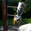
Step 3: Preparing the 510 Connector


First you need to attach wire to the positive pin on your 510. Pull the pin from the connector housing and carefully remove the rubber insulator. Now my soldering skills aren't the greatest so I find the best way to attach it is to use separate solder/flux for the job, rather than flux core as you can load up on the flux itself. Start by putting a dab of flux on the end of the pin, and on the tip of your wire, then drip a blob of solder on the pin. Use a butane torch to heat the pin which will draw the solder into the hole and quickly, before it cools insert the wire. This makes a very strong connection. Now you can re-install it into the connector with it's insulator.
Next you need to create a ground ring. You can use a washer and solder your wire directly to it, however I used some of my copper sheet to create washer with a tab. Since the cavity of the tardis is deep, I wanted to use an insulated wire connector rather than a hard solder connection for easy removal and maintenance.
Finally install your 510 connector leaving your pos/neg wires hanging out the base of the tardis.
Step 4: Wiring and Battery


Wiring;
The wiring for our mod is pretty basic with some optional components. It includes a 510 connector for attaching our atomizer, a single pull single throw push button, a toggle power switch, and a 30 amp fuse. You don't have to use the LED and resistor in the build, however It's a good indicator of the function of your mod. The LED is set to only light when the button is pressed, indicating power flowing to your atomizer.
Battery;
Battery choice is very important to a build like this. I do not recommend using anything less than an IMR 18350 rated at 30 amps high drain. Should you decide to use a battery with a different rating, or one with a different chemistry, you should adjust your fuse accordingly. Check with your local vape shop for appropriate battery types.
Caveat;
The fuse is, more or less, an optional component, as most store bought mechanical mods do not contain one, however It does go a long way in insuring the safety of your device. If you do choose to omit the fuse, please be very careful with your coil builds and battery chemistry as lithium batteries can be very dangerous, and I'd really rather not have anyone hurt themselves because of my instructable.
Step 5: Soldering and Assembly


When soldering, I like to use both a butane torch and a butane soldering iron and prefer separate solder/flux rather than flux core especially when working with recycled components that may be subject to excess corrosion.
Before you start, You need to put a 1" piece of heat shrink tube over your pos/neg wires from your 510 connector. These are for your LED as you won't be able to put them on once it is soldered into place.
First, take your coil spring, and solder it to the ground wire coming from your 510 connector. Next, drill a small hole in the end of your battery housing and screw the spring leaving one coil outside the housing. You can use some heat shrink tubing to protect this exposed end from shorting, however you should apply some epoxy to secure it from moving which should be enough on its own.
Now take the wire coming from the positive pin on your 510 connector and solder it to your push button, then take another line and connect it to the power switch, in the base. Next solder a wire to your fuse and finally to the battery terminal. (I'd already soldered the switch to the battery terminal, and ended up putting my fuse between the switch and the push button, however it's best if you put it first, in line between the switch and the terminal.)
The LED;
Optimally, it should be one wire going from the 510 to the button, with the LED/resistor attached between by removing some of the insulation from the wire, soldering them into place then covering the connections with shrink tube. Unfortunately, in my build, I made an error and cut the pos wire short, and had to make a splice. Normally I would just unsolder the wire and attach a new one, however I didn't want to risk damaging the pin in the 510. If you solder and insulate the connection properly, it may be a bit messy but shouldn't be an issue.
To solder the LED, remove 1/8" of the insulation on the wire from the pos 510 to the button and do the same on the ground from the 510 to the battery. Then solder the ground side of the LED to the ground wire. Next solder the resistor to the positive side of the LED, then attach it to the bare spot on the positive wire. Finally slide your heat shrink tubes over the connections and secure them with a lighter.
Once your LED is installed, you can install it into the hole you initially drilled in the tardis and secure it into place with some epoxy.
Step 6: Testing Your Build

Before installing your battery, you'll need to test for shorts on your build using your multimeter. Once your certain that there are no shorts, and that all of your solder joints are making proper contact, you can install the base back on your tardis. Once your base is secure, install your battery (don't screw battery door into place yet) and check the output on the 510. It can happen that when you're cramming wires into an enclosure, connections can break so if you notice the voltage dropping badly, you have a short and need to eject your battery immediately. If your voltage holds steady, you can screw your battery door into place.
Step 7: Finished


That's it. Now you can impress all of your Whovian friends with your custom tardis mod. With this setup, you can use just about any atomizer that uses a 510 connection, including hardcore RDA's if chasing clouds is your thing.
As I said before, vaping helped me kick smoking, but clouds are keeping me off of it and having some fun gear can go a long way to adding to your own enjoyment.
As usual, I hope you enjoyed the instructable and thanks for following.


