

Introduction: Upgrading Smart RGB LEDs: WS2812B Vs. WS2812


The sheer number of projects we've seen making use of Smart RGB LEDs—whether it be strips, modules, or custom PCBs—over the past 3 years is quite astonishing. This outbreak of RGB LED usage has gone hand-in-hand with a significant drop in pricing and an increased ease of use of these electronic devices.
Amongst LED manufacturers, WorldSemi has seemingly become the de facto standard amongst DIYers, hobbyists, and wearable electronics designers. The company's WS28XX family of Smart RGB LEDs includes an easy-to-use control protocol, a convenient pinout and footprint, and an incredibly bright luminescence, all within a tiny 5mm x 5mm package. But, what really has made a difference in the products' DIY market success is the $0.30 to $0.40 unit pricing in small quantities.
In the latest version of these LEDs, the WS2812B, WorldSemi yet again has made significant improvements upon its predecessor, the WS2812. Since there is very little information out there about this relatively new version, we decided to make a short Instructable to highlight the design upgrades, and advertise some of the already existing features of this nifty device!
Difficulty level: Beginner+ (some familiarity with smart RGB LEDs)
Time to completion: 5-10 Minutes
Step 1: List of Materials


To highlight the features of both the WS2812B and the WS2812 RGB LEDs, we can make use of the following parts:
1 x WS2812 RGB LED (pre-soldered onto a tiny breakout board)
1 x Solderless Breadboard
1 x Breakaway Pin Connector, 0.1" Pitch, 8-Pin Male
1 x Arduino Uno R3
1 x WS2812B Lumina Shield for Arduino
Solid Core Wire (assorted colors; 28 AWG) and Wire Strippers
Power Supply (Optional)
Both the WS2812 and WS2812B carry an embedded constant-current LED driver, as well as 3 individually controlled LEDs; one red, one green, and one blue. The LED driver comprises:
- An internal oscillator
- A signal reshaping and amplification circuit
- A data latch
- A 3-channel, programmable constant current output drive
- 2 digital ports (serial output/input)
Note:the LED driver itself is also available in a 6-pin Integrated Circuit (IC) form, which we can use to connect directly to 'non-smart' RGB LEDs of our choice; the IC in question is non other than the WS2811.
Step 2: WS2812B VS. WS2812: 4-pin Footprint (✓)


The most evident new feature of the WS2812B is a reduced number of pins (from 6 to 4), which preserve a nice size for easily soldering them (using a fine-tip soldering iron) to ~2mm x 1mm pads on a PCB. The 6 pads of the older WS2812 made it a bit difficult to route the DO pin of one module to the DI pin of the next when spacing between the modules was tight. With the WS2812B, routing the traces on a PCB is a breeze, particularly when designing arrayed configurations as the Arduino Shield shown in this step's images.
The additional space between the WS2812B pads allows for:
- Easily routing the 3 necessary signals: Power, Ground, and Data.
- Using thicker traces to connect Power and Ground, which allows for higher currents to run safely on a PCB
One important thing to note is that, for reasons we cannot fathom, the layout for the WS2812B has a little notch on the corner of the package indicating pin 3 rather than pin 1! We need to pay extra attention when soldering these by hand, so that we don't orient the module as we would with typical ICs (or the WS2812, for that matter).
*.tftable { font-size: 12.0px; color: rgb(251,251,251); width: 100.0%; border-width: 1.0px; border-color: rgb(104,103,103); border-collapse: collapse; } *.tftable th { font-size: 12.0px; background-color: rgb(23,21,21); border-width: 1.0px; padding: 8.0px; border-style: solid; border-color: rgb(104,103,103); text-align: left; } *.tftable tr { background-color: rgb(47,47,47); } *.tftable td { font-size: 12.0px; border-width: 1.0px; padding: 8.0px; border-style: solid; border-color: rgb(104,103,103); } *.tftable tbody tr:hover { background-color: rgb(23,21,21); } Pin # Symbol Function *Notch on package indicates this pin. 1 VDD Power supply LED 2 DO Control data signal output 3* VSS Ground 4 DIN Control data signal input
Another detail worth mentioning is that the Power (VDD) and Ground (VSS) pins are diagonally across one another. Thus, the traces connecting to these pins can be quite thick! However, if we make the mistake of soldering the module 'backwards', we would short Power and Ground (pin # 1 and 3). Lucky for us, as we'll see in the next step, WorldSemi has included a reverse polarity protection circuit that will prevent the WS2812B from being damaged by this error—we, of course, recommend avoiding the mistake altogether :)
Step 3: WS2812B VS. WS2812: Brighter LEDS & Improved Color Uniformity (?)

When the WS2812B was released, WorldSemi emphasized that it had brighter LEDs and better color uniformity than the WS2812. (Source: WS2812B_vs_WS2812.pdf)
However, inspecting the actual datasheets of the two devices, we can observe that the specifications for the luminance of the LEDs are identical in both:
*.tftable { font-size: 12.0px; color: rgb(251,251,251); width: 100.0%; border-width: 1.0px; border-color: rgb(104,103,103); border-collapse: collapse; } *.tftable th { font-size: 12.0px; background-color: rgb(23,21,21); border-width: 1.0px; padding: 8.0px; border-style: solid; border-color: rgb(104,103,103); text-align: left; } *.tftable tr { background-color: rgb(47,47,47); } *.tftable td { font-size: 12.0px; border-width: 1.0px; padding: 8.0px; border-style: solid; border-color: rgb(104,103,103); } *.tftable tbody tr:hover { background-color: rgb(23,21,21); }
Color Wavelength (mm) Luminous Intensity (mcd) Red 620–630 620–630 Green 515–530 1100–1400 Blue 465–475 200–400
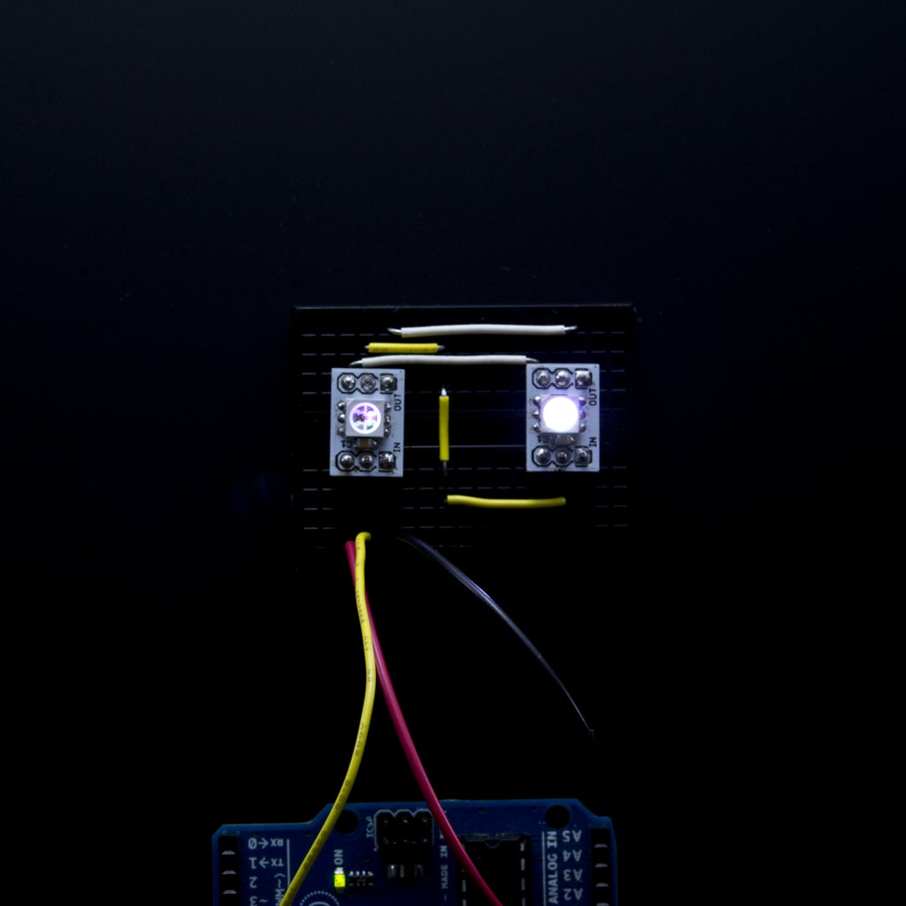
The image above shows an Arduino Uno connected to four breakout boards. Two of them carrying a WS2812B while the other two have a WS2812. We tried using standard imaging measurements to determine whether or not we could see significant differences in brightness or color uniformity, but the results were inconclusive. In order to unambiguously determine whether the two modules differ in this respect, we would have to perform some tests using an spectrophotometer. Given that we didn't have one available at the time of this writing, we can only refer to the info on the products' respective datasheets: WS2812.pdf and WS2812B.pdf
Step 4: WS2812B Vs. WS2812: Reverse Polarity Protection Circuit (✓)

We still recommend double-checking the connections and wiring before applying power to any electronic circuit, but admittedly it's nice to know that in those rare occasions where we make a mistake there is a failsafe mechanism in place to protect our precious devices.
Step 5: WS2812B VS. WS2812: Internal Structure Improved (?)
The last feature that was included in the WS812B is a separation of the two main circuits in the device: control and lighting. By separating these two, the manufacturer reports an improved heat dissipation and more robust control. This is by far the more obscure of the new features, as we do not have a good method for testing heat dissipation on a PCB.
For the improved robustness in the communication and data transfer, we didn't find any significant performance differences between the WS2812 and the WS2812B after a few simple tests we ran with the two modules side-by-side.
Attachments

Step 6: Programming the WS2812B RGB LEDs
Despite all the changes introduced in this latest version of the WS28XX family, the communication protocol needed to control its color and brightness remains unchanged from its predecessor. We can still use the great libraries developed by fellow makers from Adafruit, PJRC, and the FastSPI project.
For learning more about what really goes on under the hood of this wonderful RGB LED devices, we put together a thoroughly detailed Instructable explaining the implementation of the control protocol bit by bit (pun intended). Thanks in advance for checking it out!
https://www.instructables.com/id/Bitbanging-step-by-step-Arduino-control-of-WS2811-


