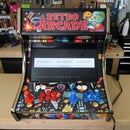
Introduction: 2-Player Stand-Up Retro Arcade


Your local Micro Center now carries everything you need to make your own Raspberry Pi based Retro Arcade cabinet. The kits are completely customizable, include the cabinet, Raspberry Pi, buttons, joysticks, audio and video accessories, and more. It's an arcade system in a box. OK, multiple boxes! They even sell a variety of vinyl wraps to customize your kit. It couldn't be easier to build your own custom arcade cabinet.
Please Note: The Retro Arcade cabinet was designed to work with many different components. This allows you to totally customize your build. We tried to think of all the configurations like monitors, speakers and different joysticks. This guide is how I made my cabinet with the components I selected. You may need to adjust your build as needed. In any case, it’s fairly easy to build and customize and should only take a day before you’ll be up and gaming! [This instructable was sponsored by Micro Electronics Inc.]
Step 1: Get the Kit

Gather all the components needed to build your Retro Arcade cabinet. You have a lot of choices, from a full-size cabinet, to a bar top version, and any combination of button colors, LCD screens and more. The free-standing cabinet comes in 2 boxes, which are fairly heavy. It's best to grab a friend to help move them around. All the parts, including the electronics, fit neatly in a medium size box that is easy to carry.
Step 2: Assemble the Side Panels


Start by assembling the two side panels. They come in two pieces for easier transportation. Simply add the two metal braces to each of the two side panels and screw them together with the four screws that are provided in the kit.
Step 3: Prep Panels & Apply the Vinyl


Next, you will dd the die-cut vinyl wrap. You can skip this step if you want a black finish, but I think the graphics add a lot of personality. Start by wiping all the panels with a window cleaner. This will help secure the vinyl in place.
Once you cut out the shape, carefully remove the backer from the vinyl. Next, starting at a corner, or edge, align the vinyl to the panel. Don't press down until it's perfectly centered. You can easily pull it up and reposition if needed. Next, using an old credit card, or gift card, start smoothing out the bubble in gentle sweeps starting from the center and moving towards the edge.
Step 4: Trim the Vinyl


Next up, carefully trim the edge of the vinyl wrap using a razor blade. I like to use one without a holder, but you can use whatever is comfortable for you. Be very careful not to cut yourself. You can hold the blade at about a 45º angle and trim the excess. It trims very easily, even around corners. Once trimmed, go ahead and wrap the other panels.
Step 5: Adding the T-Molding


You will notice that the side panels and the front panel where the joysticks and buttons are placed have a groove on the edges. This is where you will add the T-Molding. This give the edge a nice finished look and protects from wear. I like to start on the side panels and at the 90º corner. Start by pressing in the t-molding and then using a rubber mallet, gently tap it into the slot. If you don't have a rubber mallet, cover a hammer with some tape and cardboard.
Where there are very sharp corners you can cut the spline a bit to help it wrap around easier. Wrap the entire edge of both side panels. At the end, trim a little of the spline off to allow it to sit up against the starting point. The button panel is the same technique, although a lot easier since it's smaller, just make sure to wrap the 3 sides, not just the front. Once you are all done, go ahead and remove the protective plastic wrapper.
Step 6: Wrap the Button Panel

Please Note: At this point, the assembly of most of the components needed are the same for wither the bar-top or free standing kit. Some of the pictures may be from either kit.
Next, we'll wrap the panel that has the buttons and joysticks. It's easy to identify since has a lot of holes where all the buttons will be placed. Start by cleaning, then wrapping it in vinyl. Next, you have to cut small X’s where the buttons and joysticks will be inserted. Using a razor blade, make an X, then fold the vinyl down a bit.
Step 7: Adding the Button Housings


The button panel has room for all 20 buttons. Before you add any buttons, you must also remove the plastic protective covering on the corresponding plastic panel. The plastic cover protects the vinyl wrap and makes the surface very durable.
Once you clean the cover, remove the locking nuts from the plastic button housing. Next, insert the buttons, carefully noting the color and position as pictured. You insert them from the front through the plastic layer, then the wood. Once you have them all in place, flip the panel over. Next, orient them all at a diagonal. This helps wiring later. Now you can screw the locking nuts in place with the "toothed" side against the wood. It's a tight fit. If needed, you can flip a few of the locking nut over. This give you a little extra room.
Step 8: Adding the Joysticks


Next up, let's add the joysticks. You need to remove the actual stick part to attach them to the button panel. Flip the joystick over and carefully remove the spring clip with a small screwdriver or pliers. Wear safety glasses! Next, insert the body of the joystick into the opening from the back of the panel. Now you can screw the joystick in place with the provided screws. Now re-insert the stick back into the housing, flip the panel over and reinstall the retaining clip.
Step 9: Adding the Switches to the Buttons Housing


Next up, you can insert the included switches to the bottom of the button housing. Make sure to orient them correctly as pictured. Do this for both panels that have buttons. Now is a good time to double check the orientation of all the button housings.
Step 10: Adding the Audio Components


Now we can add the audio components. There is a panel in the kit that has many small slots carved into it. This is the panel for the speakers and amplifier. Start by screwing in the amplifier in the middle of the panel. Just make sure there's enough room for the speakers on each side. Speaking of speakers, now you can add both speakers centered on the openings. You can use any kind of speakers you’d like, as long as they fit within the boundaries of the panel and match the output of your amplifier.
Step 11: Mounting the Screen


The cabinet was designed to work with many different kinds of components and the screen can be mounted in a few different positions. In my case, the TV was mounted to the very top of the panel, yours may be different. The kit comes with the appropriate screws and washers to mount your monitor. Once you have a monitor mounted, you can move onto the next step, you will be able to adjust it later by opening the back panel to access the screws.
Please Note: The full size cabinet does have room to add the monitor after the cabinet is assembled. I chose to mount the screen now, because if you mount it later you will need the help of another person. If you want to add it later, simply follow the instructions above after the cabinet is fully assembled and you remove the protective plexi panel.
Step 12: Wrapping the Cover Screen

The Retro Arcade kit comes a piece of plexiglass that is used to protect the TV. It also adds a little authenticity to the overall build. The old school arcade cabinets had a similar configuration. To make the edges look a little more professional, there is an included vinyl wrap that will be added to the edges of the plexiglass. Carefully cut out the vinyl border and apply it to the edges of the plastic panel. Unlike the wood panels, once this is stuck, it's really stuck! I would suggest you have a friend help you align everything.
Step 13: Wiring Up the Speakers & TV

Now we can wire up the speakers, amplifier, and TV. The amp comes with a cable that has a left and right plug on one end, and a 3.5 mm plug on the other end. Plug the left/right in to the amp. The other end will get plugged into the Raspberry Pi.
Next, using the supplied wires, connect the speakers to the amp. The wires are color coded, so make sure they all match the color-coded connectors on the amp. Twist the wires, press the button on the amp and insert the wires. They will be held securely. The other ends get attached to the speakers. Also note the left and right speaker orientation. Now is a good time to plug in the power cable and HDMI cable into the TV.
Step 14: Assembling the Main Parts of the Cabinet


Now we can start assembling the cabinet, but not all the components. We will leave a few things off, so we can wire it up a lot easier in a later step. Start by inserting all the locking pins into all the holes on all the panels. Now you can insert all the cam locks to the corresponding parts. Note that the cam locks have a small arrow on them. This arrow should point to where the pin will be inserted.
Now you can place one side panel down on a flat surface and insert the matching cams and panels in place. There are a lot of them in this unit, take your time making sure everything lines up. Once everything is in place, including the plexiglass screen cover, lock everything down with the cam locks. You may need a short screwdriver to lock all the cams in place. The last step is to add the remaining panel on top of all the pieces and tighten everything down.
The unit is very heavy at this point. If you built it on a table you might want help getting into a standing position.
Step 15: Add Back Panel Closures


Once you stand the unit up, you can add the friction closures to the back 2 panels. These keep the panels in place and stop them from falling open. It also allows you easy access to all the electronics and monitor. The part with the 2 rollers attaches to the main cabinet, and the small bent metal piece attaches to the door.
Step 16: Attach Front Panel & Panel Hinges


The front button panel can now be added. It's secured in place with 2 hinges. Add the them to the vertical piece inside the cabinet and the button panel. You may need to make some adjustments to get the control panel to sit flat and open and close properly. You can do this by adjusting the screws on the hinge.
Step 17: Wiring, Wiring, and More Wiring!


Don't be intimidated by all the wiring. It's actually fairly simple and the specific layout can be adjusted via software on the Raspberry Pi, so exact locations of the represented A, B, X, Y, etc., is not that important. Follow the included diagram and you should be fine. Again, you can always adjust it afterwards.
Start by separating out the wires and finding the ones that have the 4 pin female connectors on one end. You will also have 1 set that has 2 female connectors. As per the diagram, wire up all the connectors to the USB board. Although the exact order isn't critical, it is critical that you don't use aground pin (GND) for a button pin. Pay close attention. The buttons have 3 pins. The closest one, which is the ground pin, the middle one, which is the input pin, or actuating pin, and the bottom pin which is closes to the wood and is NOT used.
You will be plug in the corresponding USB pin into the middle pin of the button. Again, follow the diagram for wiring. After all the button pins are wired, use the wire with a daisy chain of spade pins and 1 female pin to make the ground connections. Plug the female header pin into one of the ground pins on the USB board, and then connect either side of the player board ground pins together. They will chain together, and the order is not important. Make sure to include the 4 pins on the bottom panel too! After you do one side, use the remaining ground daisy chain to connect all the other button to another ground pin.
Step 18: Adding the Marquee

The Retro Arcade marquee is a little different than the other panels of the kit. Start by cutting out the vinyl Retro Arcade logo. Next, remove the plastic protective covering from the 2 included plastic panels. Yes, 2 this time! Attach the vinyl to 1 plastic panel. Take it slow, when it sticks, it really sticks! Next make a sandwich with another plastic panel on top of the vinyl. Now add it to the top of the cabinet. Secure in place with the included plastic channels using the included, and already attached, double sided tape.
Step 19: Adding the Power & Pi

Now you can add a permanent power strip to the cabinet. Simply use the included double-sided tape and secure the power bar in place, or screw it to an available spot inside the cabinet. There is plenty of room! Next, plug in the amp, TV, and Raspberry Pi power supply. Easy!
The last step is to add your Raspberry Pi. Plug in the HDMI cable from the TV, the included USB cable to the USB controller, the audio cable, and finally the micro USB power cable. Once you load up the emulator of your choice on the SD card, you can insert it into the Raspberry Pi and power it up.
Step 20: All Done! Final Notes.

This is a fairly straightforward build, but the build is only the beginning. Now you have to configure your Raspberry Pi to run a game emulator like RetroPi. The process is simple, and you can easily search online on how to get up and running fast. There are a lot of great games out there, including free public domain and home-brew ROMs.