Introduction: [3D Printed] Real-time Satellite Orbit Follower/Tracker With Arduino
About a week ago, I posted this project on Youtube and Reddit. Many showed interest in the project, I also did not cover any technical information about it. So, here it goes.
Here I will discuss about the "science" behind the project and then explain how you can make one for yourself.
Step 1: The Theory: Walking Through Keplerian Orbital Mechanics
Before jumping right into the project instructions, let us first take a little walk through how this system works.
The idea came to me when I noticed that all the available satellite orbit tracking software(such as: Orbitron, Gpredict and etc) work offline, but they keep asking for TLE updates all the time. After installing these software, you would only have to give your location(Longitude, Latitude) and your current local time. Utilizing the TLEs, Location & current time,the algorithm somehow manages to tell you where a satellite is right now and when will it pass over your head.
------
So, What are these TLE files?
TLE stands for "Two-Line Elements". I will quote some lines from Wiki regarding the TLE.
A two-line element set (TLE) is a data format encoding a list of orbital elements of an Earth-orbiting object for a given point in time, the epoch. Using suitable prediction formula, the state (position and velocity) at any point in the past or future can be estimated to some accuracy.
So, basically these TLE files contain pretty much all you need to calculate a satellite's positional data.
------
A bit more regarding the history of TLE from wiki again -
In the early 1960s, Max Lane developed mathematical models for predicting the locations of satellites based on a minimal set of data elements. His first paper on the topic, published in 1965, introduced the Analytical Drag Theory, which concerned itself primarily with the effects of drag caused by a spherically-symmetric non-rotating atmosphere.
Lane's models were widely used by the military and NASA starting in the late 1960s. The improved version became the standard model for NORAD in the early 1970s, which ultimately led to the creation of the TLE format.
------
Now, how does a TLE file look? Here is a demo -

------
These look like random numbers, what do they even mean?

More Details about TLE can be found on NASA's website here.
------
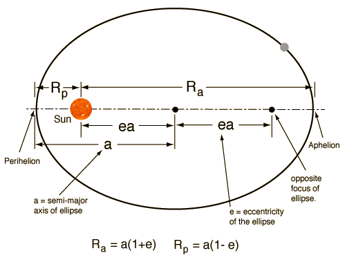
Alright, now the numbers mean something! But, what? To understand that, we need a little geometry and conics. LEO satellites orbit are of elliptical shape. let's look at an ellipse:

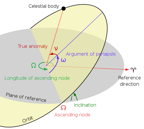
We have seen an ellipse. Now, how do we apply the idea of the earth and a satellite with this? Well, here is how:


More Details at Planetary Society website
------
Owwwwkay, now I can relate those "random numbers" of the TLE files with something real. How does the calculation really work?
Well, a few things to notice here are that, satellites have very well-defined orbits associated with them. The earth has its own rotation too, therefore the orbit of the satellite and the earth's rotation combinedly make the satellites orbit the entire earth. Without the earth's rotation, the satellite would just keep on following a well defined elliptical shape without covering all the areas of the earth.
------
Great, we have found a pattern and now there should be some kind of mechanics that we can use to calculate satellite positions, right?
Well, yes! But, I will not go into that because that is quite a huge subject to cover and I am just not qualified enough for it. I do not even claim to understand it entirely. But here is how I did it -
After doing internet research until now, I found out that all the computation is done using a mathematical model called "SGP4" and it has a FORTRAM implementation called "PLAN-13 Satellite Position Calculation Program".
Mathematical Details of SGP4: celestrak.com/NORAD/documentation/spacetrk.pdf
PLAN-13 Satellite Position Calculation Program by James Miller G3RUH: https://www.amsat.org/amsat/articles/g3ruh/111.ht...
Now, at this point, I had to replicate this application into Arduino, but hopefully, I did not have to reinvent the wheel because Mr. Thorsten Godau(DL9SEC) implemented it in C++ for Arduino. I found it in his Github.
(Yes, I emailed him regarding permission for using his Git for this project, he humbly permitted me.)
Now, let us build our Satellite follower.
Step 2: Knowing Where to Point?
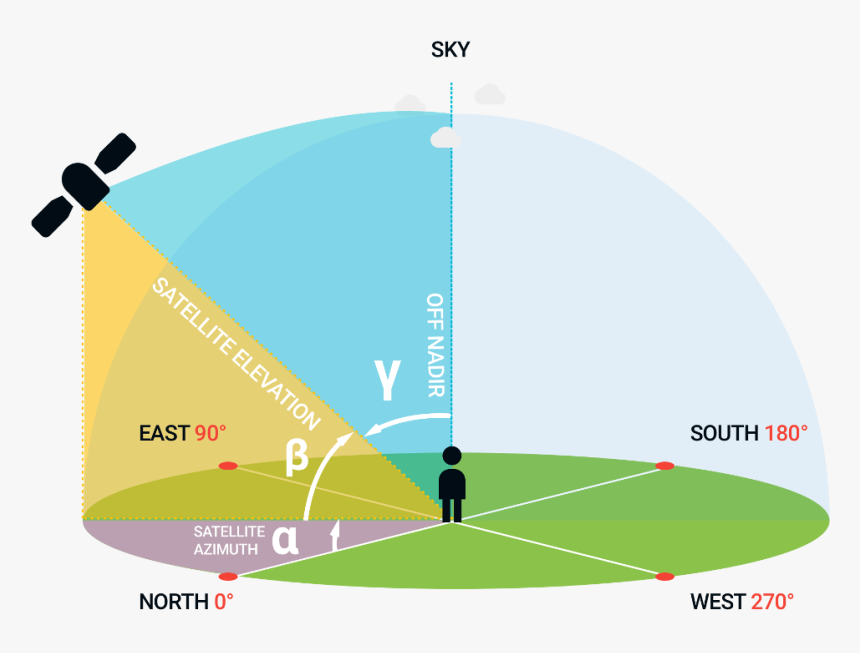
Now, we have some ideas about how the Satellite Orbital System works. Now, we need to know how can we actually point to the satellites.
For that, we need to know only 2 things.
- Elevation
- Azimuth
I will not go into explaining to them because this picture below will do it better than me.

Now, note that when the satellite is on the other side of the earth, the elevation will be negative.
We are only interested to track when it is above our horizon or when the elevation is a positive value.
Step 3: Required Materials
Software:
First of all, download everything from my GitHub: https://github.com/TNeutron/ArduinoP13/
Hardware:
For this project, we will need the following things:
- 3D Printer
- Servo Motors (x2)
- Arduino
- LEDs (preferably Red & Green)
- Resistor
- Capacitor
- Wires
Step 4: The CAD Design and 3D Printable STL Files
The Fusion360 CAD design can be found at this Github: https://github.com/TNeutron/ArduinoP13
The STL files for 3D printing can be found in Thingiverse as well: https://www.thingiverse.com/thing:4361946
Download and print them.
You need to be careful with only 1 part here. The extended walls within the marked region below were added because I was having printing issues. So, be careful while removing the support materials from this region.

Another thing that I'd like to warn you about is that, the motor will fit loose to this part because I kept a bit too much space for it. about 2mm extra. However, after printing the walls were a bit thicker because they had a support wall around the socket wall. So, I didn't change the design. Keep that in mind while printing.
If you do Fusion360, you can get the file from my Github and fix the issue.
Step 5: The Assembly of 3D Printed Parts
The Assembly process is quite straightforward, but we still have to do this carefully and maintain a few things strictly as proper directions are extremely important.
Start the assembly by first built the simple Circuit given above.
I personally do not like Instructables where they put code in attachments instead of the post, so I will post the code here directly.
Upload the following code to your Arduino:
#include <Servo.h>

Servo elevation;<br>
Servo azimuth;

void setup() {
  	elevation.attach(9);	 // Servo Motor at Top
	azimuth.attach(10); 	 // Servo Motor below
	elevation.write(0);
	azimuth.write(0);
}

void loop(){

}
Now, after uploading the code, place the base of the over the frame and put the servo exactly like the image below. (Use glue or tape to stick the motors with their slots. I used regular tape for this.)

The window-like hole should be facing exactly the opposite to the north.
Now place the motor next motor on the top and make sure it faces exactly to the north at 0 degrees.

If you followed this far properly, congratulations! The hardest portion is over.
Now, just adjust the top half circles to that the pointer can move smoothly.
The final result should look like this:

Step 6: The Code (please Check the GitHub Link for Code, Formatting Sucks Here)
After reaching this far, all that remains is to upload the code into the Arduino. Before that, you must add the Arduino Plan13 Library by Thorsten Godau(DL9SEC).
His ArduinoP13 Library with all other 3D designs can be found here: https://github.com/TNeutron/ArduinoP13
Download everything and add the library to your IDE.
Also download the Time library, if your do not already have it installed.
It can be downloaded from here: https://github.com/PaulStoffregen/Time
After adding the library, this is the code your need:
#include <TimeLib.h>
#include <ArduinoP13.h>
#include <Servo.h>
Servo elevation
 Servo azimuth;
// Current UTC [NOT LOCAL TIME]
 int CurrentHour   = 1;
 int CurrentMin    = 15;
 int CurrentSec    = 00;
 int CurrentDay    = 21;
 int CurrentMonth  = 5;
 int CurrentYear   = 2020;
// Set TLEs of your desired Satellite
 const char *tleName = "METEOR-M 2";
 const char *tlel1   = "1 40069U 14037A   20125.52516225 -.00000051  00000-0 -42286-5 0  9997";
 const char *tlel2   = "2 40069  98.5072 164.7117 0006720  56.5344 303.6479 14.20671878301977";
/* Some Frequently used TLEs: ISS (ZARYA)
1 25544U 98067A   20141.44172200  .00000634  00000-0  19412-4 0  9992
2 25544  51.6435 125.7943 0001445 337.3184 171.9893 15.49378091227714
NOAA 15
 1 25338U 98030A   20124.94794743  .00000070  00000-0  48035-4 0  9998
  2 25338  98.7208 150.2168 0011008  38.1025 322.0931 14.25962243142633
NOAA 18
 1 28654U 05018A   20124.89114038  .00000074  00000-0  64498-4 0  9998
  2 28654  99.0478 180.8944 0014042   1.3321 358.7885 14.12507537770620
NOAA 19
 1 33591U 09005A   20125.24606893  .00000052  00000-0  53375-4 0  9997
  2 33591  99.1966 129.4427 0013696 195.7711 164.3035 14.12406155579156
METEOR-M 2
 1 40069U 14037A   20125.52516225 -.00000051  00000-0 -42286-5 0  9997
  2 40069  98.5072 164.7117 0006720  56.5344 303.6479 14.20671878301977
  *
/ Set your Callsign and current location details

const char  *pcMyName = "S21TO";     // Observer name
double dMyLAT = +21.1106;    // Latitude (Breitengrad): N -> +, S -> -
double dMyLON   = +92.3278;    // Longitude (Längengrad): E -> +, W -> -
double dMyALT   = 12.0;        // Altitude ASL (m)
int rangePin = 7;   // LED for in Range Indication
  int NrangePin = 6;  // LED pin for Out of range indication
int epos = 0;
  int apos = 0;
double dSatLAT = 0; // Satellite latitude<br>
double dSatLON = 0; // Satellite longitude
double dSatAZ = 0; // Satellite azimuth<br>
double dSatEL = 0; // Satellite elevation
char acBuffer[20]; // Buffer for ASCII time
void setup(){
  setTime(CurrentHour,CurrentMin,CurrentSec,CurrentDay,CurrentMonth,CurrentYear);
elevation.attach(9)
azimuth.attach(10);
elevation.write(epos);
azimuth.write(apos)

  pinMode(NrangePin, OUTPUT)
 pinMode(rangePin, OUTPUT)
Serial.begin(9600)
 delay(10)
 digitalWrite(NrangePin, HIGH)
 digitalWrite(rangePin, HIGH)
 delay(5000)
 }
void loop(){char buf[80];
int i
int iYear = year(); // Set start year
int iMonth = month(); // Set start month
int iDay = day(); // Set start day
int iHour = hour(); // Set start hour [ substract -6 from current time ]
int iMinute = minute(); // Set start minute
int iSecond = second(); // Set start second<br>
P13Sun Sun; // Create object for the sun
P13DateTime MyTime(iYear, iMonth, iDay, iHour, iMinute, iSecond); // Set start time for the prediction
P13Observer MyQTH(pcMyName, dMyLAT, dMyLON, dMyALT); // Set observer coordinates
P13Satellite MySAT(tleName, tlel1, tlel2); // Create ISS data from TLE
MyTime.ascii(acBuffer);             // Get time for prediction as ASCII string
  MySAT.predict(MyTime);              // Predict ISS for specific time
  MySAT.latlon(dSatLAT, dSatLON);     // Get the rectangular coordinates
  MySAT.elaz(MyQTH, dSatEL, dSatAZ);  // Get azimut and elevation for MyQTH
Serial.print("Azimuth: ")
 Serial.println(dSatAZ,2)
 Serial.print("Elevation: ")
 Serial.println(dSatEL,2)
 Serial.println("");
delay(500);
// Servo calculation
  epos = (int)dSatEL
 apos = (int)dSatAZ;
if (epos < 0) {
  digitalWrite(NrangePin, HIGH)
 digitalWrite(rangePin, LOW)
  } else {
  digitalWrite(NrangePin, LOW)
 digitalWrite(rangePin, HIGH);
if(apos < 180) {
apos = abs(180 - (apos))
epos = 180-epos
} else {
apos = (360-apos)
epos = epos
}
azimuth.write(apos)
delay(15)
elevation.write(epos)
}
}(Sorry about the formatting, its kinda annoying to put code in instructable)
Step 7: References
1) NORAD Two-Line Element Set Format: https://www.celestrak.com/NORAD/documentation/tle...
2) Orbital Coordinate Systems, Part I (By Dr. T.S. Kelso): https://celestrak.com/columns/v02n01/
3) Orbital Coordinate Systems, Part II (By Dr. T.S. Kelso): https://www.celestrak.com/columns/v02n02/
4) Orbital Coordinate Systems, Part III (By Dr. T.S. Kelso): https://www.celestrak.com/columns/v02n03/
5) Greenwich mean sidereal time: https://www2.mps.mpg.de/homes/fraenz/systems/syst...
6) LEO metric to determine the ground track of a satellite: https://space.stackexchange.com/questions/2512/le...
7) PLAN-13 Satellite Position Calculation Program(FORTRAN Implementation): https://www.amsat.org/amsat/articles/g3ruh/111.ht...
8) Computing Azimuth and Elevation Angles with JavaScript: http://tiij.org/issues/issues/3_2/3_2e.html
9) Figuring out orbital positions from orbital elements: https://www.planetary.org/blogs/emily-lakdawalla/...
Step 8:

Participated in the
Arduino Contest 2020


