Introduction: 4-in-1 Arduino LCD Shield Version 2
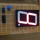


With this project, you will have at least four products in one because this kit consists of an Arduino Uno, an LCD Shield, a USB-A to USB-B cable, and all of materials that you will need to develop the following four projects: a Counter, a Thermometer, a Capacitor Meter and a 4-Channels Voltmeter. The first of them can be developed with the materials supplied while the rest of the meters will be a reality with the help of the appropriate Shield for each of them. That is, a 4-Digit Counter, a Thermometer based on LM35 sensor for measuring in both scales: Fahrenheit and Celsius, a Capacitor Meter with a scale from 100pF - 1uF, and finally a 4-Channels Voltmeter for measuring respectively in each channel a voltage from 0V - 50V.
What You Will Need:
Soldering iron and solder
Wire Cutter
Nose pliers
1 meter, 22 AWG wire
Step 1: Bill of Materials

1 Arduino Uno R3 DIP Edition (Revision 3)
1 CABLE,USB2.0,A/B,6 FEET,BLACK,USB-A MALE TO USB-B MALE
1 DFRobot LCD Shield for Arduino
1 Resistor of 220 Ω, 1/4 Watt
1 Resistor of 10 MΩ, 1/4 Watt
4 Resistors of 1 MΩ, 1/4 Watt
4 Resistors of 100 KΩ, 1/4 Watt
3 Arduino Uno Proto Shield (PCB only)
3 Pass-Through Female Headers for Arduino Shields - 1x8 and 1x6 Position (2 each)
1 Temperature Sensor LM35
1 Alligator Clip Test Leads - 2 Pack Red and Black
1 16 AWG Alligator Clip Test Leads - 2 Sets of 5 Colors (10pk)
Step 2: 4-Digit Counter
List of Materials:
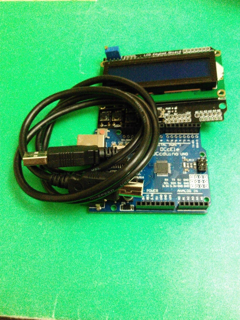
1 Arduino Uno R3 DIP Edition (Revision 3)
1 CABLE,USB2.0,A/B,6 FEET,BLACK,USB-A MALE TO USB-B MALE
1 DFRobot LCD Shield for Arduino
Step 3: Completing the Counter
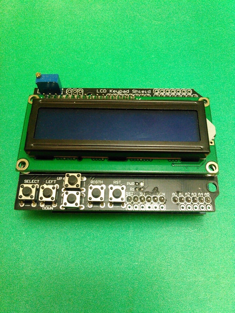
For completing this part of your project, you will only need to mount the LCD shield on the Arduino Uno by matching each of the corresponding pins.
Step 4: Uploading the Code


With this code, you will be capable of watching the numbers generated by your 4-digit Counter and you will move from one digit to four digit. Upload your code at: http://pastebin.com/GWim19yr
Step 5: Thermometer Shield

List of Materials:
1 Arduino Uno Proto Shield (PCB only)
1 Pass-Through Female Headers for Arduino Shields - 1x8 and 1x6 Position (2 each))
1 Temperature Sensor LM35
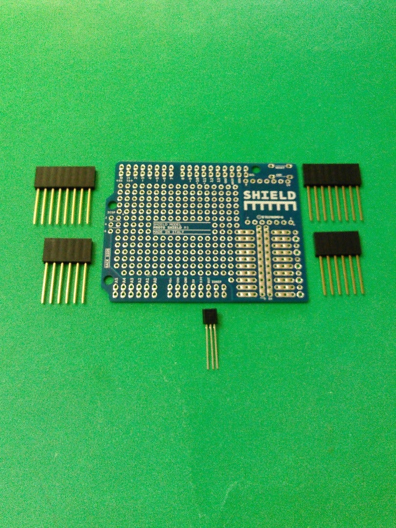
Step 6: The Arrayment of Components


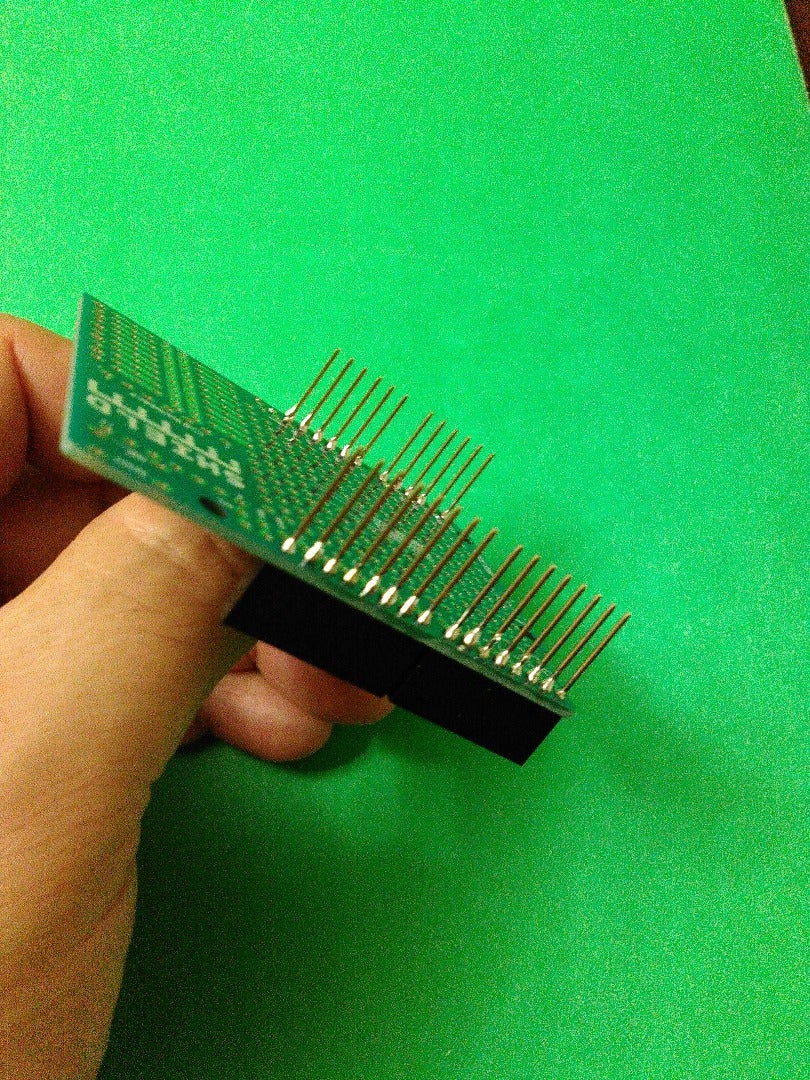
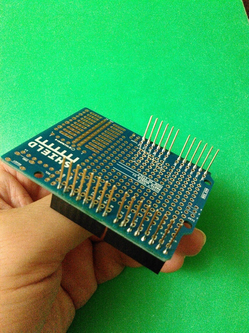
In this step, you are going to match the Pass-Through Female Headers and their corresponding pins with the PCB. Note that´s imperative that the photo in his step be observed so that you can insert the pins correctly. That is, you should insert the two 1x6 Pass-Through Female Headers in the side of the Analog holes beginning with the Analog holes and then the near six holes. Next, insert the two 1x8 Pass-Through Female Headers in the side of the Digital holes beginning with the Digital holes: D8, D9, ......... and then D7, D6, ........
Step 7: Soldering the Pass-Through Female Headers


In this step, you will insert the corresponding pins of the Pass-Through Female Headers into the PCB holes and then you will solder them.
Step 8: Knowing the LM35 Sensor

When the LM35 sensor is seen at the front, it shows its three pins: first, a +5V pin; second, a GND pin; and third, a sensor pin.
Step 9: Completing the Thermometer Shield Kit


Now, you are going to install the LM35 sensor connecting to +5V and GND its left & right terminal respectively seen it at the front while its middle end is connected to A1. Observe the previous step.
Step 10: Uploading the Arduino Thermometer Code


Once you finished the thermometer shield, stack it on the Arduino Uno and then stack the LCD shield on it. Next, upload the code at: http://pastebin.com/4fbV3fZr
Step 11: Capacitance Meter Shield

Bill of Materials:
1 Arduino Uno Proto Shield (PCB only)
1 Pass-Through Female Headers for Arduino Shields - 1x8 and 1x6 Position (2 each)
1 Resistor of 220Ω
1 Resistor of 10 MΩ
1 Alligator Clip Test Leads - 2 Pack Red and Black
Step 12: Continuing With the Capacitor Meter Shield

Carry out the step 6 and 7 again and reserve.
Step 13: Schematic Diagram of the Capacitor Shield Kit

Check the diagram of your shield and do the connections showed on it.
Step 14: Completing the Capacitance Meter Shield


For completing the shield, follow the instructions in the previous step. That is, connect one of the ends of each resistor to A1 where you will also draw the positive terminal of probe of this shield. Now, connect the remaining terminal of the resistor of 10MΩ to D2 while the remaining lead of the resistor of 220Ω to D3. Finally, draw the negative terminal of probe from GND. Remembering that you can cut the alligator clips at the measure of length what you wish.
Step 15: Installing the Capacitor Meter Shield


Once you finished the capacitor meter shield, stack it on the Arduino Uno and then stack the LCD shield on it. Next, upload the code at: http://pastebin.com/VvKrRwVk
Step 16: 4-Channel Voltmeter Shield

Bill of Materials:
1 Arduino Uno Proto Shield (PCB only)
1 Pass-Through Female Headers for Arduino Shields - 1x8 and 1x6 Position (2 each)
4 Resistor of 100KΩ
4 Resistor of 1MΩ
1 16 AWG Alligator Clip Test Leads - 2 Sets of 5 Colors (10pk)
Step 17: Continuing With the Voltmeter Shield

Repeat the step 6 & 7 again and reserve.
Step 18: Schematic Diagram of the 4-Channel Voltmeter Shield

Check the diagram of your shield and do the connections showed on it.
Step 19: Installing the Resistors


For installing the resistors, connect an end of the resistor of 10MΩ to an end of the resistor of 100KΩ leaving free the other terminals of each resistor and so form 4 sets. That is, 4 common point between the resistors where you will also connect respectively to A2, A3, A4, and A5 being these the connections to your Arduino board.
Step 20: Connecting to GND


Connect all the resistors of 100KΩ to GND, those terminales of the resistors that you will leave free.
Step 21: Resistors to A2, A3, A4, & A5


The common point of the resistors should be connected to A2, A3, A4, and A5 being these connections the interface for your Arduino board.
Step 22: Installing the Color Alligator Clips


The terminals that leave free of those resistors of 1MΩ connect them to red, white, yellow, and green alligators being these the voltages: Vr(0V-50V), Vw(0V-50V), Vy(0V-50V), and Vg(0V-50V) while the others corresponding leads of the resistors are those connected to A2, A3, A4, and A5 respectively. Note that you can cut the color alligator clips at the measure of length what you want.
Step 23: Installing the Black Alligator Clips


For installing the black alligators, connect them to GND. Once connected the last alligators, you will have completed all the outputs of voltage: Vr (0.50V), Vw (0V-50V), Vy (0V-50V), Vg (0V-50V). Remember that you can cut the alligator clips at the measure of length what you wish.
Step 24: Uploading the Arduino Voltmeter Code


Once you finished the voltmeter shield, stack it on the Arduino Uno and then stack the LCD shield on it. Next, upload the code at: http://pastebin.com/3XEfV0uu


