Introduction: Home Made Maximum Power Point Tracking (MPPT) Charge Controller | Alternative Energy


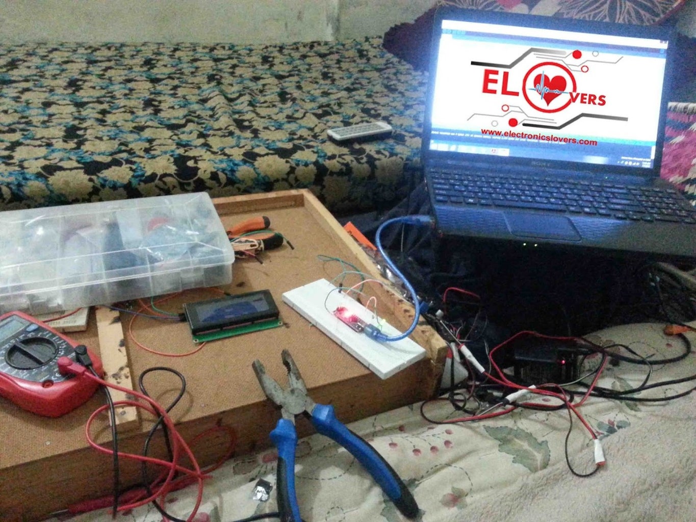

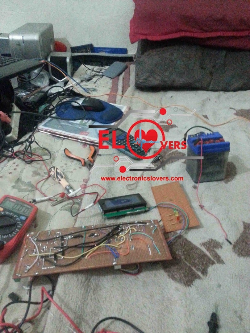
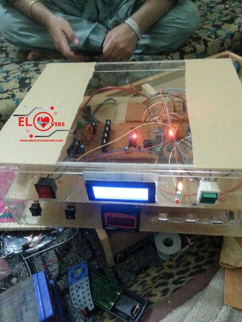
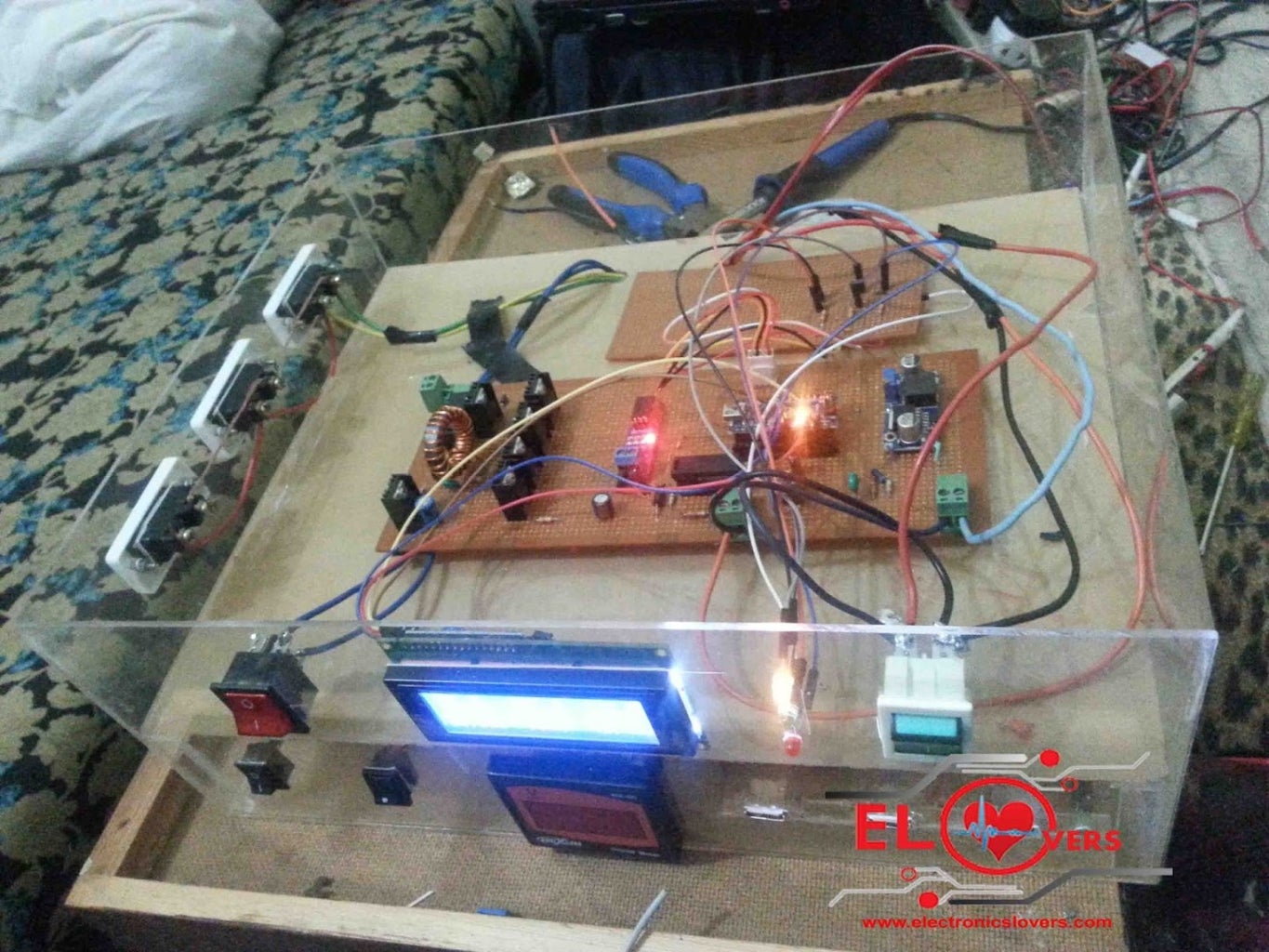


ARDUINO BASED MPPT SOLAR CHARGE CONTROLLER
For schematic and code visit my WebsiteARDUINO BASED MPPT SOLAR CHARGE CONTROLLER
what is Mppt( Maximum power point tracking)?
"we use MPPT algorithm to get the maximum available power from the Photovoltaic module under certain conditions"
How MPPT works? Why 150W solar panel does not equal to 150 w?
For example, you bought a new solar panel from the market which puts out 7 amps. under charge the setting of a battery is configured to 12 volts: 7 amps times 12 volts = 84w (P=V*I) You lost over 66 watts - but you paid for 150 watts. That 66 watt is not going anywhere, but it,s due to the poor match of the solar output current and battery voltage.
After using MPPT algorithm we can get the Maximum available power
Battery gets is now 12 amps at 12 volts Output power is equal to p= V*I p=12*12=144w Now you still have almost 144 watts, and everyone is happy.
Specification of the project 1.This project is Based on MPPT(Maximum power point tracker) algorithm 2. LED indication to show the low mid and high level of charge stat 3. LCD (20x4 character ) display for displaying power,current,voltages etc 4. Lightning /Overvoltage Protection 5. Protection For Reverse power flow 6. Over load & Short Circuit protection 7. Logging data through WiFi 8.Charge your Cellphone, tablets any gadgets throug USB port Electrical specifications : 1.Rated Voltage= 12V 2.Maximum input current = 5A 3.Load current support upto =10A 4. In put Voltage = Solar panel 12 to 24V 5.power of Solar panel = 50 Watts
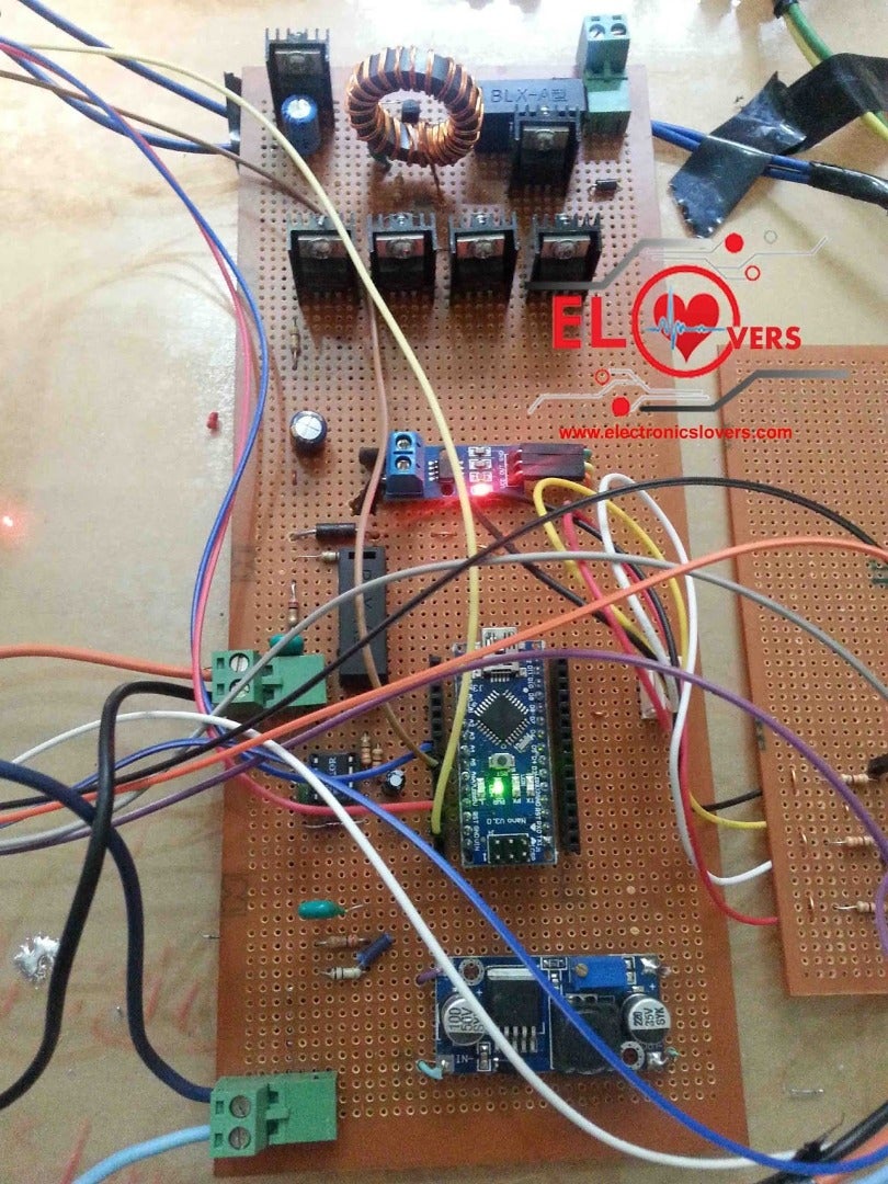
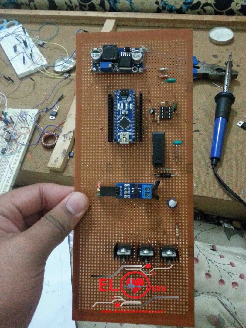
PARTS REQUIRED:
Resistors ( 3 x 200R ,3 x330R,1 x 1K, 2 x 10K, 2 x 20K, 2x 100k, 1x 470K )
TVS diode ( 2x P6KE36CA )
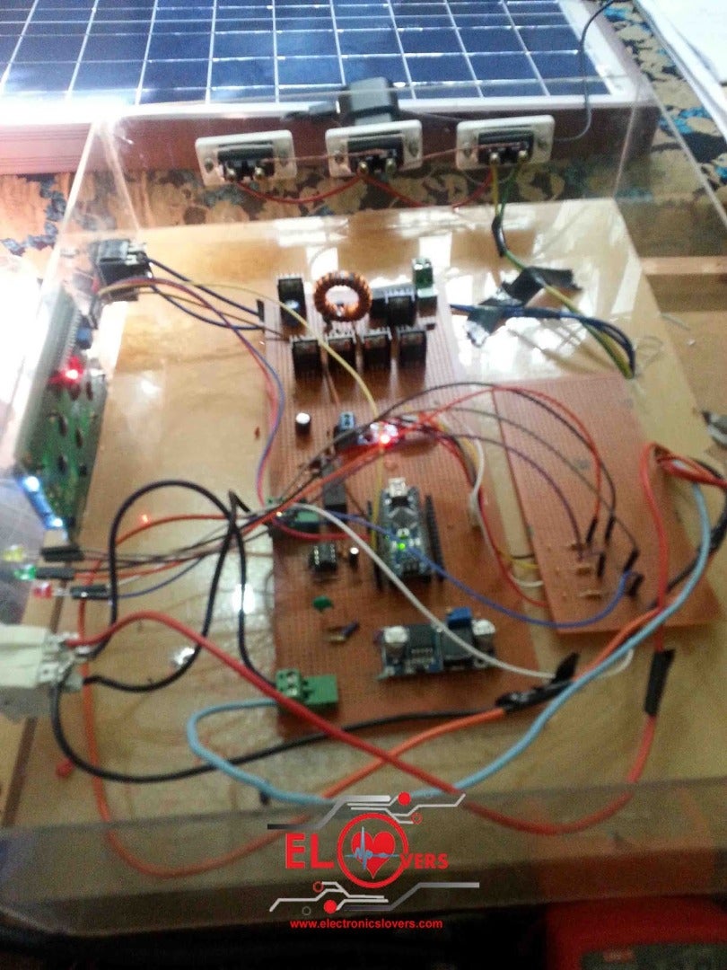
Arduino Nano
( ACS712-5A ) Current Sensor
Buck Converter ( LM2596 )
Wifi Module ( ESP8266 )
LCD display ( 20x4 I2C )
MOSFETs ( 4x IRFZ44N )
MOSFET driver ( IR2104 )
3.3V Linear regulator ( AMS 1117 )
Transistor ( 2N2222 )
Diodes ( 2x IN4148 , 1 x UF4007 )
Capacitors ( 4 x 0.1 uF, 3 x 10uF ,1 x100 uF ,1x 220uF)
Inductor ( 1x 33uH -5A )
LEDs ( Red ,Yellow ,Green )
Fuses ( 5A)
- Simulation of MPPT Charge Controller Project in Proteus software
This Simulation has been designed in Proteus Software 8.6 version. You can make your own by using Arduino Library for Proteus and a simulation tool known as Proteus. Kindly Contact Us if you want to Buy a proteus simulation source file for this project.


