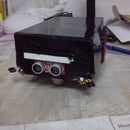
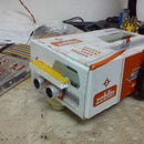
Introduction: AUTONOMOUS OBSTACLE AVOIDER
FOR THOSE ALL WHO LIKE ROBOTICS AND WANTED THAT THEIR ROBOTS CAN WORK WITHOUT MUCH HUMAN INTERFERENCE BUT WANTED TO HAVE FULL CONTROL OVER THEIR ROBOT, this the one to start with.
In this project I have used simple geared DC motors instead of servos because servos are costly, hence I have used L293D motor driver to control the DC motors, which is cheaper than buying servos.
Autonomy in ELECTRONICS is just a beginning of a new era where we can put our remotes aside and let the machine to do certain work by itself.
Step 1: PARTS REQUIRED:-
1. 2 DC MOTORS
2. L293D MOTOR DRIVER
3. 2 SMALL BREADBOARDS
4. ARDUINO UNO
5. JUMPER WIRES
6. PING ULTRASONIC SENSOR
7. 2 WHEELS
8. A FLAT BASE TO SETTLE EVERYTHING ON IT
9. 2 9VOLT BATTERIES AND A VOTLAGE REGULATOR IC
Step 2: USING L293D MOTOR DRIVER:-
L293D is a dual H-bridge motor driver integrated circuit (IC). Motor drivers act as current amplifiers since they take a low-current control signal and provide a higher-current signal. This higher current signal is used to drive the motors.
L293D contains two inbuilt H-bridge driver circuits. In its common mode of operation, two DC motors can be driven simultaneously, both in forward and reverse direction. The motor operations of two motors can be controlled by input logic at pins 2 & 7 and 10 & 15. Input logic 00 or 11 will stop the corresponding motor. Logic 01 and 10 will rotate it in clockwise and anticlockwise directions, respectively.
Enable pins 1 and 9 (corresponding to the two motors) must be high for motors to start operating. When an enable input is high, the associated driver gets enabled. As a result, the outputs become active and work in phase with their inputs. Similarly, when the enable input is low, that driver is disabled, and their outputs are off and in the high-impedance state. Pin Diagram:
Pin Description:
Pin No Function Name
1 Enable pin for Motor 1; active high Enable 1,2
2 Input 1 for Motor 1 Input 1
3 Output 1 for Motor 1 Output 1
4 Ground (0V) Ground
5 Ground (0V) Ground
6 Output 2 for Motor 1 Output 2
7 Input 2 for Motor 1 Input
8 Supply voltage for Motors; 9-12V (up to 36V) Vcc 2
9 Enable pin for Motor 2; active high Enable 3,4
10 Input 1 for Motor 1 Input 3
11 Output 1 for Motor 1 Output 3
12 Ground (0V) Ground
13 Ground (0V) Ground
14 Output 2 for Motor 1 Output 4
15 Input2 for Motor 1 Input 4
16 Supply voltage; 5V (up to 36V) Vcc 1
Step 3: SENSOR:-
Ultrasonic sensor provides an easy method of distance measurement. This sensor is perfect for any number of applications that require you to perform measurements between moving or stationary objects.
Interfacing to a micro controller is a snap. A single I/O pin is used to trigger an ultrasonic burst (well above human hearing) and then "listen" for the echo return pulse. The sensor measures the time required for the echo return, and returns this value to the micro controller as a variable-width pulse via the same I/O pin.
Step 4: CIRCUIT:-
USE YOUR OWN IMAGINATION TO DESIGN THE CIRCUIT. HERE ARE SOME BASIC POINTS FOR THE FRESHERS:
1. CREATE A POSITIVE AND NEGETIVE SUPPLY POINT ON BREAD BOARD FOR ALL VCC AND GND PINS.
2. USE BREAD BOARD INSTEAD OF PCB. BREADBOARDS ARE BEST FOR PROTOTYPING.
Step 5: PROGRAM:-
const int loopPeriod = 20;
unsigned long loopdelay = 0;
const int sensor = 12; // ARDUINO OUTPUT PIN FOR SENSOR INPUT/OUTPUT
const int bp1 = 7; // ARDUINO OUTPUT PIN FOR MOTOR INPUTS
const int bp2 = 8; // ARDUINO OUTPUT PIN FOR MOTOR INPUTS
const int bp3 = 4; // ARDUINO OUTPUT PIN FOR MOTOR INPUTS
const int bp4 = 2; // ARDUINO OUTPUT PIN FOR MOTOR INPUTS
int ultraDistance;
int ultraDuration;
void setup()
{
Serial.begin(9600);
pinMode(bp1 , OUTPUT);
pinMode(bp2 , OUTPUT);
pinMode(bp3 , OUTPUT);
pinMode(bp4 , OUTPUT);
}
void loop()
{
if(millis() - loopdelay >= loopPeriod)
{
readUltrasonicSensors();
motorstate();
loopdelay = millis();
}
}
void readUltrasonicSensors()
{
pinMode(sensor , OUTPUT);
digitalWrite(sensor , LOW);
delay(2);
digitalWrite(sensor , HIGH);
delayMicroseconds(10);
digitalWrite(sensor , LOW);
pinMode(sensor , INPUT);
ultraDuration = pulseIn(sensor , HIGH);
ultraDistance = (ultraDuration/2)/29;
}
void motorstate() // MOTOR CONTROL FUNCTION
{
if((ultraDistance > 15)||(ultraDistance < 0))
{
digitalWrite(bp3 , LOW);
digitalWrite(bp1 , HIGH);
digitalWrite(bp2 , HIGH);
digitalWrite(bp4 , LOW);
}
else
{
digitalWrite(bp1 , HIGH);
digitalWrite(bp2 , LOW);
digitalWrite(bp3 , LOW);
digitalWrite(bp4 , HIGH);
}
}

Participated in the
Robot Contest

Participated in the
Sensors Contest

Participated in the
Full Spectrum Laser Contest

Participated in the
Arduino Contest


