Introduction: Accordion Master - a Python/arduino Music Synthesizer
This project was created by a team of three student from the University of Pennsylvania at MHacks 2014 Detroit (A weekend Hackathon). The goal of this project is to create a music synthesizer that generates tones based on the user's gestures. So if you've ever wanted to create an electronic theremin, or play out your polka fantasy with a psuedo-accordion, then this project is for you!
The project will be aimed towards novices or people with starter amount of electronic knowledge, so if you're just starting out on arduino this wouldn't be a bad start! I will try to be explicit where I can about the project but if you need any more explanations or have any questions just message me :)
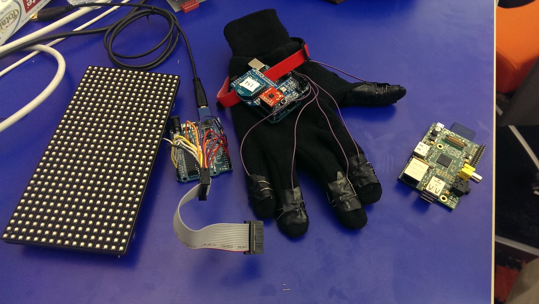
In this instructable I'll provide and cover 1) the arduino code needed to read raw values from the accelerometer, filter the data, and establish serial communication with a computer 2) parse data from a serial line, use pyFluidSynth to generate tones based on the arduino data 3) (Optional Stuff)* Port the project to a Raspberry Pi!, Use the Adafruit LED Matrix to visualize a waveform reflecting the intensity of acceleration.
All code for this project is available on https://github.com/aehernandez/Accordion-Hero
Required materials
- Arduino board (I used the Arduino Duemilanove ATmega328)
- USB A to B cable
- 3-axis accelerometer (I had the ADXL335)
- Computer (I ran this project on Linux, though Windows should be fine)
- Glove
- 22 AWG Gauge cable (or anything that fits well into the arduino board)
- Conductive Paint/Tape (or additional wire without insulation, this is basically for conducting)
Optional materials (For extended functionality):
- XBee Wireless Communication shields
- Adafruit 16x32 LED Matrix
- Raspberry Pi
Quick Overview
The end goal of this project is to have a system where the user could press their fingers together in different patterns and based on the acceleration of their hand produce a note. An important note here is that the different configuration of fingers produces varying notes and the acceleration of the hand changes the intensity of volume of the note.
Each of the four fingers (index, middle, ring, and pinkie) refers to a binary configuration. Setting a respective finger against the thumb enables a binary flag for the configuration. For example, if none of the fingers are touching the thumb then the flag is 0000 and no musical note is being played. If the index finger is contacting the thumb then it is enabled and the flag is then 0001. Depending on the implementation 0001 could refer to the C musical note. If the user only pressed their ring finger to the thumb then the flag would be 0100, and a different notes, perhaps an E would be played. In this way, the user can also contact multiple fingers against the thumb, for example the user can contact the index and middle finger against their thumb and the flag would then be 1100 which, following the pattern, could correspond to C#. Note since only 12 nodes are needed to complete a full chromatic scale, not all flags combinations will be used.
Step 1: Hardware/Electronics Setup
Before we get into the guts of coding, let's set up the hardware for this project!
(Sorry for the lack of pictures, I'll try later down the road to get some set up, but hopefully my instructions are clear)
The final goal of this step is to mount the arduino to the palm of your hand and run wires from the gloves fingers to the Arduino board.
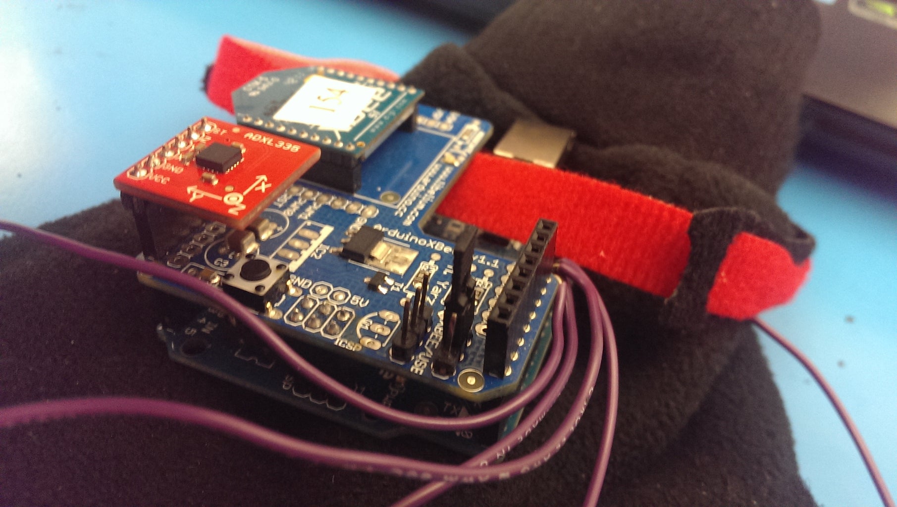
- Connect the Accelerometer to the Arduino board.
- Though your mileage may vary, if you're using the ADXL335 connect the pin labeled ST on analog pin 0, Z to analog pin 1, Y to analog pin 2, X to analog pin 3, GND to analog pin 4, and VCC to analog pin 5.
- This will be discussed more in the next step
- Get a glove. Any glove will do just make sure it fits you and you are willing to throw it away (parts of this project may damage your glove)
- Cut 5 7" wires. These wires will run from the Arduino (mounted at the center of your palm) to your fingertips. Adjust the length accordingly.
- Attach and run each wire along the underside of each finger.
- How the wires are attached are left largely up to the user. Since this project was completed in 48 hours we simply used electrical tape and glue along the insulated part and exposed the wire at the finger tips, attaching them with conductive paint to the glove.
- It is imperative that the finger tips of the glove be conductive. Any many of conductive materials can be used as long as the connect back to the arduino board via the wire. It is recommended to leave a large area so contact between fingers is easy.
- Connect the wires to the Arduino and mount the Arduino unto the palm of the glove.
- We mounted the Arduino by way of velco straps. Any non-destructive method is fine here. Use your creativity! You can come up with some really great results.
And that's all! There is a large room for creativity here, and if you're so artistically inclined you could make something really cool looking. But for now, a simple set up like the one pictured at the beginning of this tutorial is sufficient.
Note: It is entirely possible to make the glove self-contained. That means no wires running from the glove to the computer. Though this is slightly more involved, by using an external power source and a peer-to-peer xbee radio the system can be wireless! However, let's just get it working for now.
Step 2: Set Up the Arduino
Interface with the Accelerometer
Connect the accelerometer to the arduino board. If you are using the ADXL335 connect the pin labeled ST on analog pin 0, Z to analog pin 1, Y to analog pin 2, X to analog pin 3, GND to analog pin 4, and VCC to analog pin 5. If you get lost in any place, just refer to the
datasheets. Datasheets always tend to the dense side, but they're worth a close scan.The pin ST is irrelevant to our project, the X-Y-Z pins output the raw data, the GND pin is the Ground (Logical LOW or 0 Volts), the VCC is the power supply for the accelerometer (Logical HIGH). The following code sets this up in the arduino.
// Define variables to be used to process raw accelerometer values
int x, y, z, mag;
int xPrev, yPrev, zPrev;

// Constant for Low Pass filter
const double k = 0.8f;

// Define pins for ADXL335
const int xPin = 1;
const int yPin = 2;
const int zPin = 3;
const int vcc = A5;
const int gnd = A4;

void setup() {
    //Default baud rate
    Serial.begin(9600);
    pinMode(vcc, OUTPUT);
    digitalWrite(vcc, HIGH);
    pinMode(gnd, OUTPUT);
    digitalWrite(gnd, LOW);

    // Initialize variables
    x = 0;
    y = 0;
    z = 0;
    xPrev = 0;
    yPrev = 0;
    zPrev = 0;
}
We then use the analogRead(pin) function, where 'pin' is any of the 3 pins i.e. xPin, yPin, or zPin defined above to read a value between 0-1024 which tells us the value of acceleration being read. So let's start reading these values!
Filtering
This is intrinsically pretty tricky since reading acceleration from a (relatively) cheap piece of hardware like the ADXL335 is problematic. The kind of signal you're going to get from the accelerometer is going to be riddled with signal noise. This means that new accelerometer values are not to be trusted, and so we use a filter. In this particular case we use a Low Pass Filter. We want to only allow low frequency signals to pass through, values that don't differ all too much from previous readings. Note: even with complicated filtering, the error margin from a cheap accelerometer is going to be high, so integrating over time to obtain velocity and/or position from the accelerometer is going to compound this error - the values we're getting won't be accurate at all. There are also considerations for drift bias can be made, but for that is out of the scope of this tutorial. Making sense out of noisy data is a field unto its own! So let's keep it simple for now.
We add this into our program loop():
void loop() {
  // Apply a Low Pass Filter on the raw signal
  x = k*xPrev + (1-k)*(analogRead(xPin) - xAvg);
  y = k*yPrev + (1-k)*(analogRead(yPin) - yAvg);
  z = k*zPrev + (1-k)*(analogRead(zPin) - zAvg);

  // Calculate the magnitude of the force for this particular implementation
  mag = (int) sqrt(x*x + y*y + z*z);

  // Update values for next iteration
  xPrev = x;
  yPrev = y;
  zPrev = z;
}
We defined 'k' above setup(). This is a filtering constant. Feel free to tweak this constant but stay within the range 0.5 < k < 1 . Higher values means we trust new values even less, and so they'll have less an effect on our next iteration, this is what we want. You may also notice xAvg, yAvg, and zAvg. This is from a calibrate function, so lets discuss that now.Without any form of calibration the accelerometer will typically spit out values from the middle range of 0-1024. This isn't very helpful to us since we want to the relative change in acceleration from some reference point, the accelerometer's starting position. Everytime the arduino starts up, we run the calibrate() function. It is imperative that the arduino board be left alone during the time, any jostling of the accelerometer will upset the accuracy of the calibration.
Add this to the end of the arduino code:
// Function to re-zero the acceleremeter, finds an average

void calibrate() {
  int i;
  xAvg = 0;
  yAvg = 0;
  zAvg = 0;

  for(i = 0; i < calCount; i++) {
    // Read in the raw unclean data sset
    xAvg += analogRead(xPin);
    yAvg += analogRead(yPin);
    zAvg += analogRead(zPin);
  }

  // Get the average
  xAvg = xAvg / calCount;
  yAvg = yAvg / calCount;
  zAvg = zAvg / calCount;

  delay(100);
}
At the end of the day, the calibration is really just a simple average we end up subtracting from our raw values. No fanciness here.
Streaming Raw Data to be Parsed
Complete code: https://github.com/aehernandez/Accordion-Master/bl...
Step 3: Configure the Python Script
In this step we'll set up the python script whose job it is to:
- Interface with the Arduino
- Parse raw acceleration values
- Synthesize notes based on data
Preface
Here I'll be explaining in step by step how the Python script was written, but if you just want the final code to see if your system work you can get it here: https://github.com/aehernandez/Accordion-Master/bl...
This part of the instructable should be done on your desktop computer on any Linux distribution. You should have python 2.7 up and running. Any other dependencies I will cover further down. If you are so inclined it also also possible to run this program on a Raspberry Pi (in fact the Arduino code could all be ported to the Pi, which would be a good future mini-project :D ). I won't cover that in this tutorial, but if you explore that avenue don't hesitate to contact me for assistance.
In any directory create a file (with any name). For example I used in my home directory: accordian_comm.py
Interfacing with the Arduino
Two dependencies are required to interface with Python on arduino: sys and serial.
import sys
import serial

# Search for the open serial ports, the first one found is assumed to belong to the Arduino board
for i in range(256):
    try:
        ser = serial.Serial("/dev/ttyUSB{}".format(i) , 9600)
        print "Found first open serial port: USB{}".format(i)
        limit = i;
        break
    except serial.SerialException and OSError:
        if i == 255:
            print "fatal error: no open port found\nMake sure your Arduino board is connected"
            sys.exit()
            pass
In the above code we search the current system for all open ports on the baud rate 9600. One fatal assumption is that the first one open is indeed the Arduino board. While this is not the right way to do things, for most set-ups this will be correct. "/dev/ttyUSB*" is where USB devices are mapped to in the Linux OS.
What's important here is the "ser" variable which is a Serial port object to our Arduino. Looking at the pySerial documentation we see that this gives us access to functions such as read, write, and isAvailable. These are the methods we'll be using to interface with the arduino to perform serial communication.
Parsing the Arduino Data
A discussion on parsing the data in Python to come. Please refer the github code for now!
Thanks for reading!


