Introduction: All-Button Controller
I made an all-button controller for playing games. It works on pc, switch, and also some older gen consoles. With the use of an adapter it is possible to make it work on the newest Xboxes and PlayStations, however I did not do this. These styles of controllers are primarily used for playing fighting games, acting like a arcade stick but with separate buttons for each direction instead of the stick.
Supplies
- PLA
- 3mmAcrylic
- 6 M4 12mm screws amazon
- 6 M4 rivet nuts (10-12mm) amazon
- 12 low profile choc v1 switches where I got mine (variant you buy is all preference)
- 12 compatible hotswap sockets where I got mine
- 6 6x6x8mm tactile push buttons amazon
- Waveshare RP2040-zero microcontroller official websiteamazon
- USB C cable with power and data transfer (microcontroller may have one included)
- Custom PCB where I ordered from
- Optional rubber feet to stop the controller sliding and scratching your table
- Computer to flash GP2040 firmware onto the microcontroller (Flatbox rev 5 version)
- 3D printer
- Laser cutter
Step 1: Ordering the PCB
All the other part are simple to purchase, however the PCB can be more difficult as there is a whole process with many different options. Here I will explain the process for ordering from jlcpcb.
- Go to jlcpcb.com
- You will need an account so you might as well make one now
- Click either Order Now in the top right, or Instant Quote on the homepage
- Now you can upload your gerber files in a .zip with the Add Gerber File Button (The file for mine is attached)
- Once you upload the file, some of the settings should automatically fill. Here are what they should be on:
- Base Material: FR-4 (default)
- Layers: 2
- Dimensions: auto-populated, do not adjust (should be about 210x120mm)
- PCB Quantity: minimum of 5.
- Product Type: Industrial / Consumer Electronics
- Different Design: 1
- Delivery Format: Single PCB
- PCB Thickness: 1.6
- PCB Color: Preference. I used white.
- Silkscreen: This will auto-populate. If you have a white PCB it will be black, otherwise it will be white.
- Surface Finish: HASL (with lead) or LeadFree HASL
- Outer Copper Weight: 1 oz
- Via Covering: Tented
- Board Outline Tolerance: ±0.2mm (regular)
- Confirm Production File: Up to you. I recommend Yes here, because it will allow you to double-check the board to make sure everything's right before JLCPCB makes it for a minimal cost.
- Remove Order Number: I picked yes which cost slightly more. If you choose no then there will just be an order number somewhere on your board
- Flying Probe Test: Fully test
- Gold Fingers: No
- Castellated Holes: No
- PCB Assembly: No
- Stencil: No
Step 2: Assembling PCB
There are 4 main parts to assembling the PCB. The microcontroller gets soldered to the 23 middle contacts, the 6 push buttons get soldered in the top left corner, the 12 hotswaps get soldered onto the 24 contacts on the back, and the 12 mechanical switches slide into the hotswaps.
To solder the microcontroller onto the board this is the way I found easiest:
- Tape the RP2040-Zero in place so all the contacts are lined up with the ones on the pcb and make sure the bottom row is not covered.
- Solder the whole bottom row.
- Remove the tape and solder the rest not that the microcontroller can't shift out of place.
Soldering the 6 push buttons is very simple since they are just a standard through-hole component with 4 legs each.
The hotswaps can be slightly more difficult and may come off when putting in the switches if done incorrectly. If this is happens you just have to redo the ones that come off. The method I used:
- Tape the hotswaps onto the back of the board so that the left and right metal tabs go over each contact.
- Position your soldering iron so that it heats up both the hotswap and the PCB contact
- When you introduce the solder it should flow to connect the hotswap to the PCB securely
Since we used hotswaps, the mechanical switches will not need to be soldered into the board. Instead these can be pressed into the hotswaps from the front of the board. There are a few steps to do this properly and avoid damaging the parts:
- Turn the board the the front and look at where the holes are that the pins of the switch need to go into
- Line the switches pins up and carefully push them in so that neither of the pins get bent
- Push each switch all the way into the board and if any pins get bent either bend them back or use a different switch
Step 3: Flashing the Firmware
I made my PCB as a remix of the Flatbox Rev 5 by jfedor2 so I wired all the buttons to the same pins on the microcontroller so that it works with the same version of the firmware. To get this version go here and download the latest version of the flatbox rev 5 from the open source community devices section.
Step 4: Add the Button Caps
The button caps can be a bit fragile due to the shapes of the stems but I haven't had any problems with mine so far. Putting them on isn't difficult although may take some time. All you need to do to assemble them is line up the steps with the switches and push them in as far as they will go, making sure not to push on the PCB in an awkward way that may cause it to snap. You will need 1 big button cap and 11 small button caps.
Step 5: Assembling the Case
The case is made of 5 layers held together with screws and rivet nuts in 6 places. You could put the case together by hand tightening the screws however I would recommend using a screw driver for the best results. Assembling the case is very simple:
- First put layer 1 of the acrylic down and put each rivet nut under the holes
- Now one by one stack each layer on top
- The third layer is where the PCB goes, it may be tight but it should fit inside th cutout. It also has to go a specific way round since the top and botton of the outline are not the same width.
- Place layer 4 and 5 on top then put the screw in
- Once the screws are tightened you can flip the controller over and add the non-slip feet as shown
Step 6: Carry Case
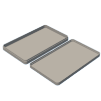
Printed the carrying case is not necessary for functionality as it is just a nice way to store or protect your controller. For printing this I recommend using a printer with a 300mm x 300mm print bed. If you are not sure if it will fit or not just bring the file into your slicer of choice and see if it fits in the area. My case was designed for using the specific rubber feet that I found at Lowes and the case is the perfect fit vertically. If you did not put any feet on your controller the case may have a bit of wiggle room up and down, and if your feet are any taller then it probably won't fit. If you have any doubts I would suggest measuring just in case.


