Introduction: An Architectural Model of a Futuristic Subterranean Building
This build is our (my colleague and I) entry to the architectural category of a past 3D printing challenge. The task for this category, rather generic I might add, is come up with a building structure that maximizes land or rather space usage in a densely built-up city. The premise is simple, to maximize land or space usage we can go one of three directions -
1. Using the spaces in between buildings. While a viable solution, it has the side effect of creating a very closed-up and cluttered cityscape. Probably this is the direction we want to avoid.
2. Using any nearby water bodies. Structures can be floating or submerged. Unfortunately this route is not available to cities which lie inland.
3. Using spaces underground. This option does has the advantage of not adding to an already crowded cityscape. It is also the most likely option available to most cities. The problems being that the construction will be costly and structure not scalable (once constructed, it is near impossible to expand).
To us it seems that the third option is the most attractive of the lot, but only if we manage to come up with an idea to solve the problem of cost and scalability. After literally hours of bouncing ideas around we finally hit upon the golden nugget so to speak. Wait for it.... A building that burrows into the ground with modules can be added to it as it burrows, allowing the building 'grow' with time. This building will have three essential components -
1. It will be shaped like a corkscrew, so that it can burrow?
2. The 'corkscrew' part will be made up of modules (each containing living quarters or habitation modules as we like to call it, for example). These modules are added as the building burrows deeper, increasing the capacity of the building over time.
3. There will be some kind of massive overhead roof structure that will serve to collect and bring sun light and rain water into the center of the building. Solar panels mounted on the massive surface of the roof will augment the electricity needs of the building?
At the same time we started our design process, we took to the internet to try to find the answer to the question whether there are any existing building or design that has this spiral feature on such a massive scale. We did not find any. Most buildings (for example the Guggenheim museum in New York) have segmented spiral ramps connecting only adjoining floors, with a flat landing at every floor.
As we proceeded with designing the building, we pretty much covered the technical aspects (the 'structural design', the proportions and all the jazz). But the question of what 'kind' of building is it going to be still remains. This question deals with the very heart and soul of the building. It determines how the occupants will feel upon entering it and what lasting impression will it gives. For us at least the answer seem to be clear. We want the building to give whoever that enters it a sense of awe. A sense of being part of something greater. How in real life will such a building look? Once again we turned to the internet for an answer.
An excellent example we found that sort of illustrates what we are going for is the Ponte City Tower, Johannesburg, South Africa. Do a search for images of it and you will see what we mean. It is simply a surreal sight either looking down from the top or up from the base of the central column. Unfortunately, the building had a turbulent history, but things are improving from what I gathered. For an excellent short documentary of the daily life in Ponte City Tower check out 'Ponte Tower' by Philip Bloom.
As for the challenge, unfortunately, victory eluded us on this count. Due to time constraint, the model needs to be scaled down significantly in order for the print to be complete on time. The FDM printer simply did not have the required resolution for this print.
For the FORMLABS CONTEST - Architecture and architectural models are a very big part of our maker interest. This episode (one of our very first attempts in 3D printing) taught us a very important lesson. For very large architectural models fused deposition modeling (FDM) printers are great with the big build volume. But sometimes we need models that are compact, indeed most of the time for our case. Something which we can bring around or just to place on the desk for inspiration. In such case FDM printing is grossly inadequate. Probably only selective laser sintering (SLS) 3D printers with their high resolution will suffice. That is where Form 1+ 3D printer will come in extremely useful for us.
This is probably a good time to mention that we are not architects, nor did we receive any training in the finer nuances of architectural design. I can imagine our design has violated a lot of the cardinal rules associated with architecture. But we attempt to make our design as realistically functional as possible. Here we document our design and build efforts.
Step 1: Conceptualization, Design, and Modeling
Conceptualization
Before embarking on the task of designing such an underground building, there are a few potential pitfalls that need to be addressed. They are -
1. Non-Scalability - Underground structures are hard to scale up, especially in terms of going deeper
2. Construction Cost - It is in general more expensive to build underground than above ground.
3. Psychological Factor - There are possible negative psychological impacts with prolonged underground habitation.
Our Solution -
We 'believe' the architectural design we came up with addresses the above issues while solving the problem of land constraint. It is based on the working principle of an earth auger. It consists of a central shaft surrounded by a helical structure.
At the base of the central shaft there is a massive boring head to remove the soil from beneath it. Similarly there are four overlapping boring heads at the end of the helical structure. The entrance lobby block which serves as the main entrance to the building also contains powerful hydraulic ramps to assist in the boring motion of the whole structure.
The key to the versatility of our building lies in the modular design of the habitation block. The entrance lobby block stays fixed on the surface. As the whole structure bores into the ground, space is created between the lobby and the first habitation block at the beginning of the helical structure. A new habitation block can then be installed periodically. The sides of the central column are also built up. This allows a scalability in terms of space in the building.
Design
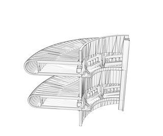
For every complete round in the central shaft there are 10 habitation modules. Access to each habitation block is via the main spiral ramp (1:12 gradient, conform with some building code I think) which runs throughout the building. An integrated elevator and stairwell allows occupants to access each habitation block no more than 5 modules away. At the back of each habitation block is a massive service corridor which also runs throughout the length of the building. It is used to transport the excavated soil to the surface and serves as an evacuation route in case of emergency.
To further drive home the message that 3D printing can be an efficient mean of manufacturing, these modular habitation blocks can conceivably be constructed via concrete 3D printing at an offsite location. The central shaft can also be printed in a similar fashion by a printer running along the circumference of the shaft. We believe large scale implementation of 3D printing here will bring down the cost of constructing the building.
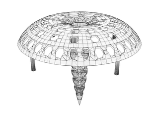
The whole underground building is covered by an umbrella-shaped roof structure. The hexagonal holes are solar panels which will produce power to augment the usage by the occupants. The central column serve as a structure for rain water collection which can be later used for various non-potable purposes, or can be diverted to create indoor rain in the central column. More importantly the column also divert sunlight into all parts of the building during daytime for illumination, thus mitigating the negative psychological impacts with prolonged underground habitation.
The scale of our design here is 1:266. Each habitation approximately contains a living space of 150 square meters. There are 40 modules in the building (for this model), including the 1 entrance lobby block and 2 service and boring block at the bottom of the helical structure.
Modeling
The model was drawn in Solidworks. As the major theme of the building surrounds a corkscrew, we used 'Helix and Spiral' command under 'Curves' to draw a spiral segment of the appropriate length (for the individual module, spiral has a gradient of 1:12 and an angular sweep of 36 degrees is used). Using 'Swept Boss/Bass' we draw the basic shape of the each of the block. Various details were then added later.
***Warning***
The uploaded .STL files here have NOT been tested in anyway for compatibility. They are uploaded more as a reference. If you plan to print it anyway, probably some slight modifications are needed. This series of files also do not have the cut-away that allows one to see the building from the side as shown in the photos. For that refer to the next section.
Step 2: Fabrication
The 3D printing facilities were provided by a local high school. The architectural model was fabricated using the process of FDM. Printing was done on two separate FDM printers both with the following specification:
1. Position Accuracy: X/Y: 0.025mm and Z: 0.005mm
2. Print Nozzle Diameter: 0.4mm (compatible with 1.75mm diameter PLA and ABS plastic filament)
3. Build Volume: 202mm (X) x 162mm (Y) x 157mm (Z)
All in all pretty standard specs for a cheap FDM printer. Earlier work done to characterize the printers has revealed that they can print reliably down to a resolution of at most 1 mm (calibration problem probably). Therefore during the design phase, all the interlocking parts were given 0.5 mm clearance on each side and that no structures were smaller than 1 mm.
Removal of the supporting structure was of a great concern to us, as it might potentially interfere with the actual model. Initially, we planned to print each of the habitation module in two parts, a top and bottom section. These would eliminate the need for support structures for the over-hanging roof. We deemed that the assembly of the two half and the central column adds negligibly to the total time taken.
However, when we started our printing we found that at the optimized printer settings, each module took approximately 3 hours to complete. Due to student usage in the day time, only one of the printer is available. Thus we made the painful decision to assemble the model in Solidworks and scale it by 55% for printing in 4 large blocks. The roof section was split into three sections.
The model was printed with white 1.75 mm PLA extruded at a temperature of 195 degree Celsius on to a Kapton tape covered platform heated to 55 degree Celsius for ease of removal.
The .SLDPRT files (Solidworks parts file) for the designs were converted to .STL files. These files were later re-scaled and converted to gcode via Cura which also generated the print instructions for the filling structures in the solid portion of the model and the supports for the overhanging structures in the model. The gcodes were then ported over to repetier-host that interfaces with the actual printer. The combined printing time is approximately 48hrs. Layer height of 0.1mm and a fill factor of 20% for faster printing.
For the removal of the support structure, we basically went in with pliers to remove the larger chunks of the support layers. For finer cleanup, we use tweezers and watchmaker screwdrivers to pry away the smaller support structures. As one might imagine, this resulted in significant damage to parts of the model. The surfaces supported by the support structures were also extremely rough. Probably if you attempt to print this, a smarter orientation and support structure setting is required.
***Take Note***
The .STL files uploaded here to serve as reference. They were not tested extensively for printability. The .STL here includes the cut-away that allows one to see the inside of the building. At the 1:1 scale the smallest structure can probably reach 0.1 mm. One would need a 3D printer capable of that resolution.
Step 3: Assembly
Compared to the herculean effort of the support removal and cleaning up the model, the assembly was a relative breeze -
1. The model pieces were glued together using cyanoacrylate glue. Minimal sanding was done to remove the glue lines. The same was repeated for the three-part roof structure.
2. The assembled model was then placed in the acrylic stand before the stand was glued together using acrylic glue. 3. Like a cherry on a cake, the roof was just placed on the acrylic stand (this allows for removal so that one can see more of the details in the central columns)
Step 4: A Virual Tour
Now here comes the last step of this instructables (well not really a last step as such, but just for fun), let's take a virtual tour of the finished building (the running order of photos for this tour goes from left to right and top to bottom) -
1. Imagine yourself standing below the sprawling flight of stairs leading up to the entrance the building. The building has been burrowing autonomously for nearly a month now, all in all about 40 modules, habitation and service modules included, are already in place. Today is the day when the rest of your team will move in to install all the electrics and the minute trimmings that will finally make the building come alive. You arrived an hour before the work is scheduled to start just to soak in the scene of the empty and bare building for the last time. It is about to get much more bustling in the days to come.
You started by climbing up the bare and unfinished concrete steps towards the main entrance lobby. On your left is the gigantic service corridor that will be sealed with a massive hatch hiding it away from the prying eyes of the occupants.
2. You walked through the entrance lobby and exit the other flight of stairs. You turned around and look at the lobby you just passed through. With the morning sun filtering through the entrance, you reminded yourself that this will be a sight many will see daily on their way out as they go about their daily routine.
3. You slowly stuck your head over the parapet on the other side and was treated with an almost vertigo inducing sight of the whole central column. You can see that all the unfinished and dormant habitation modules. The central inverted spire loomed menacingly right in front of you. Soon it will be fitted with miles of fiber optic cables and computer-controlled reflectors, all in an attempt to replicate the natural movement of the sun across the sky in the central column. Pumping from top side will serve to replicate natural rain in the central column. Greenery will cover whole surface of the spire, giving this spire of light and rain an organic look.
4. You made your way to the back of one of the habitation modules to get a better perspective of the space and view of the outside through the panoramic front windows. When the building is operational, the prefabricated habitation modules will be practically livable before being fitted to the superstructure.
5. You exited the module and continued your tour, only turning occasionally to look back at the long elegant spiral ramp that leads all the way to the entrance lobby.
6. You continued your walk all the way to the last module, a service module which houses the massive motors that drives the side boring heads. The hatch to the module is partially open allowing you to hear the soft hum of the churning electric motors. Ahead of you the spiral ramp leads to the entrance of the bottom boring head.
7. You stepped out from the ramp towards the base of the inverted spire and looked up to find a magnificent sight of the spire and the roof. You suddenly heard someone whistled from the direction of the entrance lobby - the rest of your team has arrived, it is time to get to work...
Often this kind of architecture illustrations paint pictures of the completed building with it's inhabitants. But this is well beyond my illustration skill at the moment.

Participated in the
Formlabs Contest


