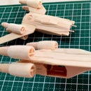
Introduction: (And Finally Another Not So) Mini LAAT/c Popsicle Stick Model
What good is a 'Tank' if it cannot be deployed to battle quickly? Here's a complementary addition to the recently posted project on a mini popsicle stick AT-TE... A LAAT/c or Low-Altitude Assault Transport/Carrier.
The LAAT/C was a heavy lift vehicle used by the Grand Army of the Republic during the Clone Wars. First introduced during Star Wars Episode II (Attack of the Clones), the vehicle was the main transport operated by the Galactic Republic throughout the animated Clone Wars Series. The dropship was easily distinguishable from it's smaller, troop-transport version due to it's huge, heavy lift arms mounted beneath the wings.
Another 'huge' project, the LAAT/c wiped out my entire stock of tongue depressor-sized popsicle sticks. I will be replenishing this vital resource for future builds.
Step 1: Materials and Tools
Like the AT-TE, a lot of tongue depressor-sized popsicle sticks were used for this project. The huge wings were almost the entire length of a stock popsicle stick. The fuselage was made up of three sections glued together to make up its entire length. Various sizes of dowels made up the engines, gun mounts, piping and parts of the heavy lift magnetic clamps. Other small parts came from my spares box.
Tools used for this build were:
- Dremel 3000 with the following attachments and accessories:
- Dremel's workstation and flex tool shaft
- Coarse and Fine Drum sander
- Fine disc Sander
- Standard & reinforced cut-off wheel
- #500 Aluminum Oxide abrasive wheel
- #953 Aluminum Oxide grinding stone
- #83702 silicone carbide grinding stone
- #125 high speed cutter
- X-acto cutter with #11 blade
- Olfa Cutter
- Fine tweezers
- Mechanical pencil
- Ruler
- Various Clamps
- Elmers White Glue
- Cutting mat
- 'Third-hand' jig
For this build, I compared the cutting capabilities of the X-acto and Olfa Cutters. The blades of the Olfa Cutter were noticeably sharper than the #11 X-acto blades although The latter's pointed edge proved more useful for pinpoint drilling on flat surfaces. The Olfa cutter's grip was also more comfortable to work with. Anyway, that's just me...
Step 2: Schematics and Images
Schematics in the internet were rather lacking for the LAAT/c. Only one useful schematic from deviantart.net was used in this build. But even this single reference does not identify the major components of the vehicle so I had to speculate on the function and designation of some of the parts.
In order to get an approximate scale with the AT-TE project, schematics of the 'Tank' were superimposed on top of the LAAT/c's deviantart profiles.
Google images keywords used were "LAAT/c" or "AT-TE carrier". Like schematics, images returned did not show details although several pictures from blogs.c.yimg.jp were extremely useful, particularly the position of the AT-TE 'hanging' from the LAAT/c. Below are the URL's of images and schematics I referenced for this project:
http://media.moddb.com/images/articles/1/171/170633/auto/1414202943LAATc_zpsc1280556.jpg http://blogs.c.yimg.jp/res/blog-d0-7e/nikonikohoshizora/folder/1289073/85/37389685/img_2?1318018754 http://blogs.c.yimg.jp/res/blog-d0-7e/nikonikohoshizora/folder/1289073/85/37389685/img_1?1318018754 http://blogs.c.yimg.jp/res/blog-d0-7e/nikonikohoshizora/folder/1289073/85/37389685/img_4?1318018754 http://blogs.c.yimg.jp/res/blog-d0-7e/nikonikohoshizora/folder/1289073/85/37389685/img_0?1318018754 http://blogs.c.yimg.jp/res/blog-d0-7e/nikonikohoshizora/folder/1289073/85/37389685/img_5?1318018754 http://orig01.deviantart.net/8d49/f/2016/085/2/6/low_altitude_assault_transport_carrier_ortho__new__by_unusualsuspex-d9w7dh7.jpg http://vignette4.wikia.nocookie.net/theclonewiki/images/d/d1/SecondGeonosis-Scale-1-.jpg/revision/latest?cb=20111124192722 https://66.media.tumblr.com/35eabf422642140f12e3cd0cd2f897e7/tumblr_inline_nbc7xzNSwH1rq44i1.jpg
Again, my deepest appreciation to the folks providing those amazing and useful images. Cheers!
Attachments
Step 3: Main Fuselage Assembly
The LAAT/c's main fuselage consisted of sixteen (16) layers of tongue depressor-sized popsicle sticks at its widest point. The widest end contained the dropship's chin mounted, forward-facing guns.
Of the sixteen (16) pieces, eight (8) made up the vehicle's central, main spine with the front gun mounts accounting for the rest of the layers (four on each side of the front gun mounts). Patterns were initially traced based on the profile illustrations from the deviantart schematics. The main shape of each piece was cut using an Olfa Cutter before building up the layers with Elmers white glue. The 'spine' was sanded smooth using a combination coarse/fine drum sander and a #500 aluminum oxide grinding wheel attachment on a Dremel 3000.
To complete the LAAT/c's profile, additional, laminated layers were glued to the vehicle's front and rear ends. The unusual front gun mounts and single pilot's cockpit were carved using a combination coarse/fine drum sander attachment and finished with a #500 aluminum oxide grinding wheel attachment on a moto tool.
Step 4: Wing and Engine Sub-assemblies
The two-piece wing was traced directly onto a tongue depressor-size popsicle stick using the top-view schematics from deviantart as reference.
After the pieces where glued and sanded smooth, lines were scribed onto the flat surface to provide some detail to an otherwise featureless, flat surface. A #83702 silicone carbide grinding stone was used to scribe the lines on the wing surface.
Each single-piece engine was directly cut from a medium-sized dowel using a reinforced cutting wheel attachment. The same attachment was used to scribe a notch near the front end of the cylindrical engine. The tapered, rear-end of the engine was made using a fine grit drum sander attachment on a moto tool. A #125 high speed cutter was used for the engine's intake and exhaust ports. Finally, a #953 aluminum oxide grinding stone was used to finish the front engine intake nozzle.
Since I had no information on the component above the rear fuselage, I speculated that this part was a 'thruster housing'. The shape of the thruster housing was traced from the top-view deviantart schematics. Three (3) layers of scrap popsicle sticks were cut, laminated and shaped like a bullet for the thruster housing. Another layer of scrap was used for the thruster housing mount that connects the part above the rear fuselage.
More speculation for this part, a pair of laser guns mounted below the thruster housing. These were made from toothpicks cut and shaped using a standard cutting wheel and finished with a fine disc sander attachment.
The engines were glued to the side of the long fuselage's rear end. The wings were glued next using the front-view of deviantart's schematics as guide for the approximate angle. A 'third-hand' jig came in handy to hold the fuselage in place while the glue hardened.
With the wing assembly in place, the thruster housing was glued on top of the rear fuselage between the two (2) cylindrical engines. The pair of laser guns were glued on the sides of the thruster housing mount.
As a preparatory step to the fabrication of the heavy lift-assemblies, the square-shaped wing mounts were cut from tongue depressor-sized popsicle sticks and glued underneath the huge wings. The wing mounts provided an additional bracing between the angled wings and the main fuselage.
Step 5: Heavy Lift Sub-assemblies and Other Small Parts
With the wing mounts in place, a pattern was traced onto a tongue depressor-sized popsicle stick for the heavy-lift 'arms'. Three (3) layers comprise each 'arm' with each layer cut into shape with a reinforced cutting wheel attachment. The final shape was finished with a combination, fine/coarse drum and fine disc sander attachment on a Dremel moto tool.
The tiny, dome-shaped gun mounts were shaped from the ends of a wooden dowel. The chin mounted gun turrets were glued in place. The single, rear mounted laser gun mount was glued to the rear end of the fuselage during the final stage of the build.
The magnetic clamps that provided the link between the AT-TE's central articulated joint and the LAAT/c's lift arms were from a spare fabricated dowel from the previous project. The dome-shaped connector was carved to fit the depression in the AT-TE's central articulated joints. A fine drum sander/ disc sander attachment was used to shape the dome of the magnetic clamp. A reinforced cutting wheel was used to detach the shaped clamp from the wooden dowel. A piece from a wooden dowel provided the housing that was glued to the base of each clamp. The connecting rods that linked the magnetic clamp housing to the lifting arms were cut from a single toothpick. Finally, the connecting rods were glued at opposite ends of the magnetic clamp housing.
I fabricated a movable lifting arms cylinder since it would be easier to position the magnetic clamps to the arm during the final build. For the lifting arms cylinder, a wooden dowel from the crafts store was fabricated into a rolling pin-shaped piece with the use of a combination of fine drum sander and #9936 structured tooth tungsten carbide cutter attachments. The piece was detached from the wooden dowel using a reinforced cutting wheel.
For the lifting arms wing mounts, spare popsicle sticks were used. A pilot hole was drilled using a #9934 structured tooth tungsten carbide cutter and finished with a #953 aluminum oxide grinding stone attachment on a Dremel 3000. The ends of the lifting arms cylinder should fit snugly into the hole for the lifting wing mounts.
The heavy-lift arms were glued to the lifting arms cylinder and allowed to dry for the final build.
Step 6: Completing the Build
For the final step, the AT-TE was test-fitted under the completed fuselage and wing sub-assemblies to confirm the 'scale' of both vehicles. I have to cut a piece from the long fuselage 'spine' since I overestimated the overall length of the AT-TE.
Traingular, front and rear covers for the square shaped bottom wing mounts were cut from spare popsicle sticks. They were glued in place after adjusting the final shape of the front and rear covers using a fine disc sander attachment.
For the top wing bracket, tongue depressor-sized popsicle sticks were cut using an Olfa cutter and glued from the edge of the cylindrical engines to the top middle wing. Triangular front and rear covers for the top wing bracket were cut from spare popsicle sticks and glued in place. I used a combination fine drum and disc sander attachment to remove excess wood from the front and rear covers.
The lifting arms wing mounts were glued below the wing with the lifting arms cylinder wedged between the two pieces. The arm should swing freely below the wing when the glue dries.
Probably the most difficult part of the build was attaching the magnetic clamps sub-assembly to the ends of the lifting arms. The dome of the magnetic clamps should line up with the AT-TE's central articulating joints. This means having the LAAT/c dangle above the AT-TE while the magnetic clamp was glued to the lifting arm. I needed to scratchbuilt a pair of sixteen (16) layer popsicle stick blocks to prop up the LAAT/c with the AT-TE temporarily mounted to the magnetic clamp sub-assembly. I used a 3M double sided tape to temporarily mount the magnetic clamp assembly to the AT-TE's central articulating joints.
Spare tongue depressor-sized popsicle sticks were fitted and trimmed using an Olfa cutter to cover the triangular, front and rear spaces of the bottom wing mounts.
For the top wing braces supporting the engines to the wing, spare tongue depressor-sized popsicle sticks were traced from the deviantart front view images, fitted, trimmed using an Olfa cutter and glued on top of the wings. Similarly, spare tongue depressor-sized popsicle sticks were fitted and trimmed using an Olfa cutter to cover the triangular, front and rear spaces of the top wing braces.
The detached pilot's canopy was glued back to the 'reduced' fuselage of the LAAT/c. The dome-shaped rear gun mount was glued to the rear of the LAAT/c.
Additional details were the two (2) layer front bulkhead just behind the pilot's canopy, a circular 'hydraulic regulator' on the side of the LAAT/c's 'spine', small, cylindrical 'hydraulic cylinders' mounted on the sides of the front bulkhead and small, connecting pipes between the 'hydraulic cylinders' and the bottom wing mounts and front and rear laser gun barrels. Again, the 'hydraulic' regulators & cylinders were just a guess on my part since the schematics does not label the various components of the LAAT/c.
The completed LAAT/c doesn't look much but the dropship with the attached AT-TE turned out quite impressive. I'll be replenishing my tongue depressor-sized popsicle sticks supply after this. I think I'll be going back to smaller vehicles in future posts...


