Introduction: Android Controlled Robot for Beginners (A to Z)
Do you like Robots? Are you new in Robotics? Do you thinking to build a Robot from scratch? If yes, this instructables is for you. In this instructables I will show you how you can build a robot from scratch, I also show you how you can control you robot using your Android phone. I will guide you to build an android application to control your robot via bluetooth. Don't worried, you don't need any programming experience to build android app because I will use MIT App Inventor to build an android app.
I am sure If you follow this, you will able to build Line Following Robot, Obstacle Avoiding Robot and so on. So, let's start working.
Step 1: Stuff Required
Hardware :
- Arduino / Arduino Clone or make your own custom arduino board with this tutorial.
- Two DC gear motors like this (Robotshop).
- A ball caster (Sparkfun)
- Two robot wheels (Sparkfun)
- Chassis, usually a small acrylic board will do.
- HC-05 Bluetooth Module (Amazon)
- Four AA batteries and battery holder.
- L293D Motor Driver IC
- Small breadboard
- Some nuts and bolts
Software :
- Arduino IDE : Arduino
- MIT App Inventor 2
Why DC Geared Motor?

The speed of motor is counted in terms of rotations of the shaft per minute and is termed as RPM. Another important parameter of a motor is torque. Torque is a force for which rotor or shaft rotates. The more the torque, the shaft can rotate with more load. Generally a DC motor run with a high speed and low torque which is not perfect for robotics applications. Most robots required high torque with a low speed. The gear assembly helps in increasing the torque and reducing the speed. Using the correct combination of gears in a gear motor, its speed can be reduced to any desirable figure. This concept where gears reduce the speed of the vehicle but increase its torque is known as gear reduction.
To know more about motor please see my instructables: Complete Motor guide for Robotics
Ball Caster
The wheel is the most common moving element among other possibilities including legs, flying, swimming and rolling. A wheel provides at least speed, accuracy and stability for a robot, three characteristics very important in designing and build robots. Finding inspiration in everything, the researchers design many types of wheels including standard, orientable, ball, and omnidirectional wheels.
Depending on the design and requirements, standard wheels are used especially for classical methods of driving and steering while orientable and ball wheels are included in the same category and user for balancing a robot.
A ball caster is a type of 'wheel' that allows smooth movement in all directions. Ball caster works as omnidirectional wheels and are very good for driving and steering and are used when the robot should have the ability to move in all directions. The ball can be builded from metal or plastic and is positioned on the frame with a holder.
HC-05 Bluetooth Module
Bluetooth is a wireless technology standard for exchanging data over short distances (using short-wavelength UHF radio waves in the ISM band from 2.4 to 2.485 GHz) from fixed and mobile devices, and building personal area networks (PANs). Range is approximately 10 Meters (30 feet).
The HC-05 Bluetooth modules are based on the Cambridge Silicon Radio BC417 2.4 GHz BlueTooth Radio chip. This is a complex chip which uses an external 8 Mbit flash memory (datasheet). These low-cost Bluetooth Sub-modules work well with Arduino and other Microcontroller as Master or Slave. The module has two modes of operation, Command Mode where we can send AT commands to it and Data Mode where it transmits and receives data to another bluetooth module.
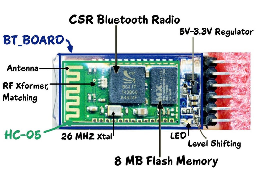
The module has two modes of operation, Command Mode where we can send AT commands to it and Data Mode where it transmits and receives data to another bluetooth module.The default mode is DATA Mode, and this is the default configuration, that may work fine for many applications:
Baud Rate: 9600 bps,
Data : 8 bits, Stop Bits: 1 bit, Parity : None, Handshake: None
Passkey: 1234
Device Name: HC-05
To know more details about HC-05 module visit: arduino-info.wikispaces.com
Why Motor Driver?
Could you remember maximum current capacity of an Arduino I/O pin? Yes, maximum current capacity of an arduino I/O pin is 20mA. Could you imagine, how much current a simple CD drive motor can draw? A simple 5V CD drive motor can take more than 200mA, 10 times larger than an arduino pin can safely handle. So, how can we drive a DC motor using arduino? Yes, you are right! We have to use transistor between arduino pin an DC motor to safely drive a DC motor using arduino or other microcontroller.
DC motors normally have just two leads, one positive and one negative. If you connect these two leads directly to a battery, the motor will rotate. If you switch the leads, the motor will rotate in the opposite direction.
If you want to run a DC motor in single direction only than you have use only one transistor. But you have to run a DC motor in either direction than you have to use 4 transistors in H like fashion generally called H bridge. A H-bridge can control the direction of the spin of DC motor, without changing the way that the leads are connected. H-bridges are used in many different applications, one of the most common being to control motors in robots. It is called an H-bridge because it uses four transistors connected in such a way that the schematic diagram looks like an "H." You can use discrete transistors to make this circuit, but H-bridge IC package is available. One most common H-bridge IC is L293D widely used in robotics.
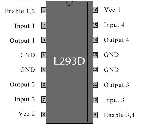
L293D Motor Driver IC
L293D is a 16-pin IC which can control a set of two DC motors simultaneously in any direction. It means that you can control two DC motor with a single L293D IC. The l293d can drive small and quiet big motors as well. There are two Enable pins on l293d. Pin 1 and pin 9, for being able to drive the motor, the pin 1 and 9 need to be high. For driving the motor with left H-bridge you need to enable pin 1 to high. And for right H-Bridge you need to make the pin 9 to high. If anyone of the either pin1 or pin9 goes low then the motor in the corresponding section will suspend working. It’s like a switch. Speed of a motor can be increased or decreased by continuous giving high and low signal to enable pin. Generally, we connect enable pin of IC to a PWM output pin of Arduino.
There are 4 input pins for l293d, pin 2,7 on the left and pin 15 ,10 on the right as shown on the pin diagram. Left input pins will regulate the rotation of motor connected across left side and right input for motor on the right hand side.
Logic Table
• Pin 2 = Logic 1 and Pin 7 = Logic 0 | Clockwise Direction
• Pin 2 = Logic 0 and Pin 7 = Logic 1 | Anticlockwise Direction
• Pin 2 = Logic 0 and Pin 7 = Logic 0 | Idle [No rotation] [Hi-Impedance state]
• Pin 2 = Logic 1 and Pin 7 = Logic 1 | Idle [No rotation]
Voltage Specification
Vcc1 is the voltage that it needs for its own internal operation 5v; L293D will not use this voltage for driving the motor. For driving the motors it has a separate provision to provide motor supply Vcc2 (pin 8). L293d will use this to drive the motor. It means if you want to operate a motor at 9V then you need to provide a Supply of 9V across Vcc2 Motor supply.
The maximum voltage for Vcc2 motor supply is 36V. It can supply a max current of 600mA per channel.Since it can drive motors Up to 36V hence you can drive pretty big motors with this l293d. VCC pin 16 is the voltage for its own internal Operation.
Attachments
Step 2: Make Chassis (part 1)
Readymade chassis that are available in the market are really good, cheap and for all you know they might have been subjected to a R&D before fabrication. In spite of all these advantages I still see the following issues with readymade chassis.
- They are not available the shape and size that I feel fit for my robot. Most of the time I am forced to restrict the robot size to the size of the chassis that is available.
- They do not give the flexibility that a custom design can have.
- You cannot cast your artistic touch (if you have one that is) over the design.
- Above all, they are not unique. If you go for an event with high hopes and find that there are a dozen robots that looks exactly like yours, then you will understand the importance of being unique.
So the only other alternative is to build your own chassis. There are wide varieties of materials to choose from when it comes to building your own chassis. I have listed out the commonly available materials over which robots are built.
Wood: Wood is the easiest and cheapest material that is also strong enough to support the weight of a large robot. Most of the time robots are built on wood. Wood is preferred because it is easily available. You can walk into a building under construction and you will have enough and more wood to for all the robot’s you can possibly build in a month’s time. The reason they are chosen is that they are really easy to work with.
Plastics: Most people like to use acrylic Plexiglas sheets in place of glass for transparent applications and small robot bases because it is easy to drill and tap and can be cut with a jigsaw. PVC (pipe) can be useful for projects where lightweight strength is needed. Plexiglas, PVC, and most other plastic can be formed or shaped using heat gun.
Metal: It is hard to beat metal for building a robot frame. It is extremely strong, durable, and can be joined by either welding or using bolts/nuts. Cutting is a bit more difficult, requiring either a hacksaw (and some elbow grease) or a reciprocating saw with a fine-tooth metal blade. Once built, a metal frame will last for years and will not warp or change shape.
Fiberglass: Fiberglass is an outstanding material for creating specific shapes that would be nearly impossible to make from metal or wood. It is also extremely strong and rigid once set, as well as waterproof. The process involves laying a fiberglass cloth and then applying a two-part resin on top of the cloth. It only takes about 1 hour to harden, but it does make some strong fumes.
Details: http://embedjournal.com/
Though wood has more advantages this post will cover the use of acrylic as the material for building chassis. Acrylic is available in all shapes and sizes with a wide range of thickness to choose from. One other compelling factor is that it available in vibrant colors which gives a new visual appeal to you robot.
Take two pieces of acrylic sheet, one is round shape and another is rectangular shape as shown in above image. Make drill and connect together using nuts and bolts. Use glue to connect motor to the rectangular box.
Though I used homemade robot chassis, it is not mandatory to make your own robot chassis for the project. You can by robot chassis from any hobby shop as according to your own choice.
Step 3: Make Chassis (part 2)
Using 3 inches nuts fix two board together as like as figure. Nuts can be smaller then 3 inch or bigger than 3 inches, it depends on your requirements and choice. Use supper glue to connect two gear motor to the bottom board. After connecting two boards and motor, connect the wheel to the shaft of the motor. Your chassis is ready!
Step 4: Schematic & Layout
Circuit connection is very simple for the robot. We need to connect two motor to the Arduino using H-bridge motor driver IC L293D. L293D has 16 pins. It has 6 input pins for two motors. Connect two enable pins with two pwm pins of arduino board. Connect another 4 pins to any 4 digital pins of arduino. Don't forget to change the arduino sketch accordingly. Now, connect 4 output pin of the IC to two motors. Our motor's connection is completed. Now, connect 9 V battery to the Vcc2 pin (pin # 8) and arduino 5 V pin to Vcc1 pin (pin # 16) of the IC. Make a common ground connection among battery, IC & arduino board. It's very important.
Now, it is the time to connect bluetooth module to the arduino board.
HC-05 is a serial port module which makes it very easy to use. If you see the pin configuration of HC-05, there are total 6 but we only need 4 middle ones for our set-up.
- Connect VCC with 5V of Arduino
- Connect GND with any GND of Arduino
- Connect Rx pin with Tx of Arduino
- Connect Tx pin with Rx of Arduino
Rx & Tx connection is a bit confusing? The matter is that the data transmitted by arduino's Tx pin is received by bluetooth module's receive (Rx) pin. For the reason arduino Tx is connectd bluetooth Rx pin and so on.
Now power-up the Uno using USB cable, a red light LED on HC-05 will start blinking, means we are ready to go forward to the next step!
Attachments
Step 5: Connecting All Electronics
In the previous step I showed & explained how to connect arduino, bluetooth module, motor driver IC & motors. In this step I will show you the physical connection with images. First put H-bridge IC to the breadboard and make connection to arduino with jumper wires. Then connect two motors previously adjusted with robot chassis. Then connect serial bluetooth module with Tx and Rx pin (pin # 0, 1) of arduino. You may connect it with another arduino pin but for that you have to use software serial library. I used pin 0 & 1. Now make ground connection to all the devices. In the final stage connect 9V battery to the motor driver IC. Congratulation!!! your connection is completed. You are ready to program.
Step 6: Making App
App Inventor is a web based free and easy to use android application development environment. No previous programming experience is required to develop android app using App Inventor. You will require a gmail account to start with App Inventor.
There are two forms of Bluetooth – classic Bluetooth, which we use in the sample applications, and a newer version known as Bluetooth low energy, Bluetooth BLE, Bluetooth LE or Bluetooth Smart – all referring to the same new technology. The newest Android devices running Android 4.3 or newer, usually support the newest Bluetooth Smart technology. Regardless, we use classic Bluetooth which is backwards compatible to older phones, and is the technology supported by App Inventor.
IMPORTANT – not all Bluetooth modules will work with App Inventor! While new versions of Android support all versions of Bluetooth, App Inventor (at the time of this writing) supports “classic” Bluetooth only. In particular, App Inventor does not support the newer Bluetooth LE (Low Energy) version.
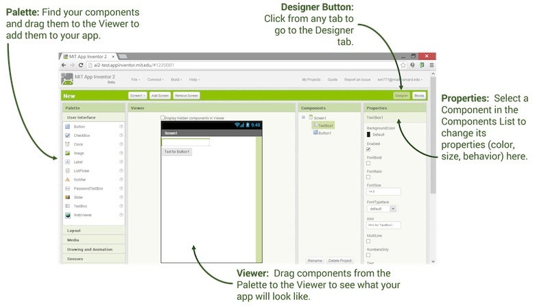
To develop app in App Inventor you have to work with two environment, the Designer and the Blocks Editor.
App Inventor Designer
The Design Window, or simply "Designer" is where you lay out the look and feel of your app, and specify what functionalities it should have. You choose things for the user interface things like Buttons, Images, and Text boxes, and functionalities like Text-to-Speech, Sensors, and GPS.
App Inventor Blocks Editor
Block Editor is used to define the app's behavior by putting blocks together.

We have gathered basic knowledge about app inventor. So, let's start to design a program to control our robot.
To get started go to App Inventor
1. Go to the web: http://ai2.appinventor.mit.edu/ and log in with a gmail account.
2. Click Continue to dismiss the splash screen
3. Start a new project, give a name without any space
4. The Designer will open.
5. Add a Label, a ListPicker, 5 Buttons, a Slider and another Button.
6. Then add two Non-visible components (BluetoothClient1 & Notifier1)
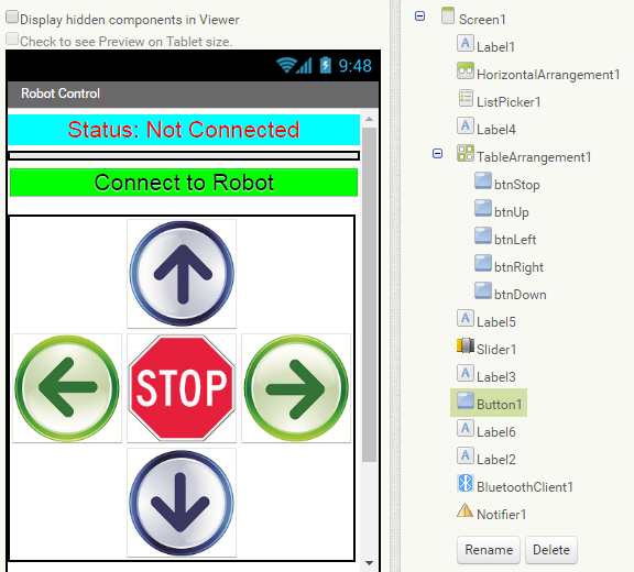
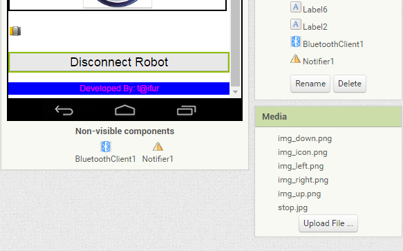
7. I used 5 images for five buttons (4 arrows & 1 stop), you have to upload image in media section first to do that.
Our UI design is completed. Now, we have to define the behavior of UI component's from Block Editor.
1. App Initialization: The first step is to check that Bluetooth is activated or switched on. If not, an error message is displayed reminding the user to open Android’s Settings and then switch Bluetooth to on.
The Initialize event occurs when the app is launched – and this is a good place to check whether or not Bluetooth is enabled on the device.

2. Connecting: When the device is running, the user selects the device name from a list of available Bluetooth devices. Because the list of devices is in the form of a list, the ListPicker is a great interface component to display the device list and handle the selection. Before the list is displayed, the list is filled with the list of Bluetooth devices (AddressesAndNames).

After the device has been selected with the ListPicker user interface, the Connect method of BluetoothClient1 establishes the connection. The method returns a value of true if the connection was successful. If connection become successful then change the Label1 text to 'Status: Connected' in Green color.

When disconnect button is click BluetoothClient1 become disconnected and Label1 text changed to Status: Not Connected in red color.

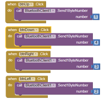
When anyone from 5 control buttons (Up, Down, Left, Right & Stop) is clicked then it sends 1 byte unique number to the receiving device (HC-05 connected to Arduino).

When slider position become changed it sent the current position to the receiver.

If you followed all the steps your app is now matured enough to interact with you and as well as your robot. It is the high time to make a .apk file for your mobile phone and transfer it to your device.
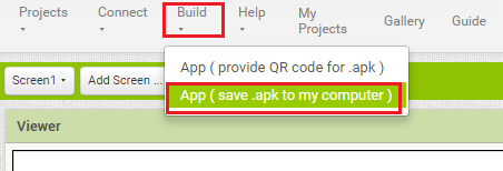
Click to Build menu and select save .apk to my computer. A .apk file will be generated and downloaded to your computer. Transfer it to your mobile phone and install in your device.
Complete source file (.aia) is attached below. You can import it to your App Inventor account from project menu and modify it as your desire.
Step 7: Uploading Program
You made all the connection? Just upload the program to your Arduino Program
/*
 * created by Md. Khairul Alam
 * Control 2 DC motors with Smartphone via bluetooth
 * 2015
 */
int motor1Pin1 = 3; // pin 2 on L293D IC
int motor1Pin2 = 4; // pin 7 on L293D IC
int motor1EnablePin = 6; // pin 1 on L293D IC
int motor2Pin1 = 8; // pin 10 on L293D IC
int motor2Pin2 = 9; // pin 15 on L293D IC
int motor2EnablePin = 11; // pin 9 on L293D IC
int state;
int Speed = 100;
int flag=0;        //makes sure that the serial only prints once the state
int stateStop=0;
void setup() {
    // sets the pins as outputs:
    pinMode(motor1Pin1, OUTPUT);
    pinMode(motor1Pin2, OUTPUT);
    pinMode(motor1EnablePin, OUTPUT);
    pinMode(motor2Pin1, OUTPUT);
    pinMode(motor2Pin2, OUTPUT);
    pinMode(motor2EnablePin, OUTPUT);
    // sets enable1Pin and enable2Pin high so that motor can turn on:
    //digitalWrite(Motor1EnablePin, HIGH);
    //digitalWrite(Motor2EnablePin, HIGH);
    // initialize serial communication at 9600 bits per second:
    Serial.begin(9600);
}

void loop() {
    //if some date is sent, reads it and saves in state
    if(Serial.available() > 0){
      state = Serial.read();
      if(state > 5){
         Speed = state;}
      flag=0;
    }
    // if the state is '1' the DC motor will go forward
    if (state == 1) {
        forword();
        if(flag == 0){
          Serial.println("Go Forward!");
          flag=1;
        }
    }

    // if the state is '2' the motor will turn left
    else if (state == 2) {
        turnLeft();
        if(flag == 0){
          Serial.println("Turn LEFT");
          flag=1;
        }
        delay(1500);
        state=3;
        stateStop=1;
    }
    // if the state is '3' the motor will Stop
    else if (state == 3 || stateStop == 1) {
        Stop();
        if(flag == 0){
          Serial.println("STOP!");
          flag=1;
        }
        stateStop=0;
    }
    // if the state is '4' the motor will turn right
    else if (state == 4) {
        turnRight();
        if(flag == 0){
          Serial.println("Turn RIGHT");
          flag=1;
        }
        delay(1500);
        state=3;
        stateStop=1;
    }
    // if the state is '5' the motor will Reverse
    else if (state == 5) {
        backword();
        if(flag == 0){
          Serial.println("Reverse!");
          flag=1;
        }
    }
    //For debugging purpose
    //Serial.println(state);
}

void forword(){
    digitalWrite(motor1Pin1, HIGH);
    digitalWrite(motor1Pin2, LOW);
    digitalWrite(motor2Pin1, LOW);
    digitalWrite(motor2Pin2, HIGH);
    analogWrite(motor1EnablePin, Speed);
    analogWrite(motor2EnablePin, Speed);
    //Serial.println("Go Forward!");
}

void backword(){
    digitalWrite(motor1Pin1, LOW);
    digitalWrite(motor1Pin2, HIGH);
    digitalWrite(motor2Pin1, HIGH);
    digitalWrite(motor2Pin2, LOW);
    analogWrite(motor1EnablePin, Speed);
    analogWrite(motor2EnablePin, Speed);
    //Serial.println("Go Reverse!");

}

void turnRight(){
    digitalWrite(motor1Pin1, LOW);
    digitalWrite(motor1Pin2, LOW);
    digitalWrite(motor2Pin1, LOW);
    digitalWrite(motor2Pin2, HIGH);
    analogWrite(motor1EnablePin, Speed);
    analogWrite(motor2EnablePin, Speed);
    //Serial.println("Turn Right");

}

void turnLeft(){
    digitalWrite(motor1Pin1, HIGH);
    digitalWrite(motor1Pin2, LOW);
    digitalWrite(motor2Pin1, LOW);
    digitalWrite(motor2Pin2, LOW);
    analogWrite(motor1EnablePin, Speed);
    analogWrite(motor2EnablePin, Speed);
    //Serial.println("Turn Left");

}

void Stop(){
    digitalWrite(motor1Pin1, LOW);
    digitalWrite(motor1Pin2, LOW);
    digitalWrite(motor2Pin1, LOW);
    digitalWrite(motor2Pin2, LOW);
    analogWrite(motor1EnablePin, Speed);
    analogWrite(motor2EnablePin, Speed);
    //Serial.println("Stop");

}

Participated in the
Robotics Contest 2016

Participated in the
Make it Move Contest 2016


