Introduction: Arduino Car - Bluetooth Controlled


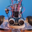


This is an Arduino based car which can controlled easily with your phone. This is fairly cheap to make and very easy to make for beginners as there is minimal wiring. This car is fast and can drive well on carpet. This uses and easy to use app that sends commands to the arduino via bluetooth and it processes these commands to move. This is farly cheap and if your not new to arduino, then you will only need to buy a couple things.
Supplies
Phone (android) with this app
Arduino motor driver shieldHC-05 Bluetooth module
Robot motor chassis (2 motors included)
9V battery x 2 (preferably rechargeable)
9V battery adapter/wireOPTIONAL
Mini breadboardRGB Led (cathode)
Step 1: Coding the Arduino

Download Arduino IDE from the website here: https://www.arduino.cc/en/software
Select your operating system and follow the download instructions (you don't have to donate, there is a button to select "Just Download")
I prefer to code the Arduino first with nothing plugged into it because it is easier for me.
If you don't want to copy and paste this then download the code in the file and open with Arduino IDE.
If you are not using an rgb led, the code will still work fine
Here is the code:
#include
SoftwareSerial BlueTooth(0, 1);
char BT_input;
char Incoming_value;
int buzzerpin = 4;
int E1 = 10; //enable is = speed. 0 = off. 255 = max speed
int M1 = 12; //m = direction
int E2 = 11;
int M2 = 13;
int rpin = A5; int r;
int gpin = A4; int g;
int bpin = A3; int b;
void setup() //This block happens once on startup
{
Serial.begin(38400);
BlueTooth.begin(38400);
pinMode(buzzerpin, OUTPUT);
Serial.begin(38400);
pinMode(M1, OUTPUT);
pinMode(M2, OUTPUT);
pinMode(E1, OUTPUT);
pinMode(E2, OUTPUT);
}
void loop() {
analogWrite(rpin, r);
analogWrite(gpin, g);
analogWrite(bpin, b);
if (BlueTooth.available()) {
BT_input = BlueTooth.read();
if (BT_input == 's') {
moveStop();
Serial.println("Motors are Off");
r = 255; g = 0; b = 0;
}
else if (BT_input == 'b') {
moveBackward();
Serial.println("Moving backwards");
r = 255; g = 116; b = 23;
}
else if (BT_input == 'f') {
moveForward();
Serial.println("Forward");
r = 0; g = 255; b = 0;
}
else if (BT_input == 'r') {
moveRight();
Serial.println("Turning right");
r = 255; g = 255; b = 0;
} else if (BT_input == 'l') {
moveLeft();
Serial.println("Moving left");
r = 0; g = 200; b = 255;
}
else if (BT_input == 'd') {
Serial.println("dancing");
dance1();
}
}
}
void moveForward() //This function tells the robot to go forward
{
Serial.println("");
Serial.println("Moving forward");
digitalWrite(M1, HIGH);
digitalWrite(M2, HIGH);
digitalWrite(E1, HIGH);
digitalWrite(E2, HIGH);
}
void moveBackward() //This function tells the robot to move backward
{
Serial.println("");
Serial.println("Moving backward");
digitalWrite(M1, LOW);
digitalWrite(M2, LOW);
digitalWrite(E1, HIGH);
digitalWrite(E2, HIGH);
}
void moveLeft() //This function tells the robot to turn left
{
Serial.println("");
Serial.println("Moving left");
digitalWrite(M1, LOW);
digitalWrite(M2, HIGH);
digitalWrite(E1, HIGH);
digitalWrite(E2, HIGH);
delay(150); //if You increase this value, it will make the turns bigger, if your reduce this, the turns will be smaller
moveStop();
}
void moveRight() //This function tells the robot to turn right
{
Serial.println("");
Serial.println("Moving right");
digitalWrite(M1, HIGH);
digitalWrite(M2, LOW);
digitalWrite(E1, HIGH);
digitalWrite(E2, HIGH);
delay(150); //if You increase this value, it will make the turns bigger, if your reduce this, the turns will be smaller
moveStop();
}
void moveStop() //This function tells the robot to stop moving
{
Serial.println("");
Serial.println("Stopping");
digitalWrite(M1, LOW);
digitalWrite(M2, LOW);
digitalWrite(E1, LOW);
digitalWrite(E2, LOW);
}
void dance1() { //this is just a small dance I made
for (int z = 0; z < 2; z++) {
moveForward();
delay(1000);
for (int i = 0; i < 7; i++) {//wiggle
moveLeft();
delay(150);
moveRight();
delay(150);
r = random(0, 255); g = random(0, 255); b = random(0, 255);
analogWrite(rpin, r); analogWrite(gpin, g); analogWrite(bpin, b);
}
moveBackward(); delay(1000);
}
moveStop();
}
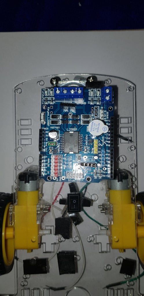
Step 2: Wiring the Arduino


The arduino wiring is very minimal. Hover over the images for small details/help.
Don't plug in the motor shield onto the arduino just yet. Get your HC-05 bluetooth module and insert it into the 4 pin holes that have the text bt2 underneath (fig 1). When plugging this in, make sure that there is a pin on either side of the black header that is not inserted because these pins are not necessary (fig 2) . Look at the pictures for help. Make sure you have initialized AT mode correctly on the bluetooth module, if not then here is a link because this is necessary for this to work (make it a slave module). There should be a switch included so either solder a wire to the middle and any of the side pins, or hook a wire through the switch's pin and then bend the wire (fig 3). Do this for the middle and any end pin and connect any one of them into the ground (GND) of the Arduino and the other one to 5V (fig 4.). On the motor shield board, there is a small blue block with a screw on top that has the writing "VMS" and "GND" (fig.5). Get the 9V battery clip connector and push the red wire into the hole that has VMS underneath like in the pictures and screw it down fairly firmly (fig 6). Then plug the black wire into the hole that has GND underneath like in the pictures (fig 6). With the front wheel of the robot facing forward, plug the left motors wire (the one closer to the top) into the far right one of the blue block terminals (fig 7). Then plug the left motors wire which is closer to the ground at the one to the second on the right (fig 8). Then the right motors top wire in the second to the left, and then the left motors bottom wire to the far right one. Screw these in and if you didn't understand, look at the pictures for help. There is also a four block to plug in wires for the motors instead of screwing them in, they are exactly the same, i used this instead. Just plug exactly the same as the screw terminal does if you are using normal wires. Then plug in the 9V battery (fig 9) into the battery clip and i have a choice for you:
Would you rather have the arduino powered separately from the motors. if so then look at fig and pull out the green connector. (fig 10)
or
would you like to only use one battery to power the motors and the arduino. then plug the green connector in the slot any way round like in the pictures. (fig 11) This will drain the battery quicker.
Now place the arduino shield onto the arduino like in the pictures above. Make sure it is inserted correctly and that there are no pins protruding underneath (all the shields pins are inserted into the arduino). (fig 12 and 13)
Step 3: Putting It All Togeher


Get the robot chassis and get some bluetack or something sticky to hold down the arduino in the middle next to the switch. The you can stick the wires down if you want to tuck them away. you can also stick the 9V batteries in underneath the chassis but if it doesn't stick properly, then stick it next to the arduino. You can also add a cover over it and decorate it, but I haven't.
Step 4: OPTIONAL: RGB Led


If you have an RGB led (cathode) and 3 220 ohms - 1 k ohms resistor (any resistor between the two values) and 4 male to male or 4 male to female jumper wires then you can add a light which can change colour. In the picture, I have labeled which pin of the RGB led is for what. The longest pin is for ground. Plug the RGB led into the breadboard like in the picture and then plug tin the resistors across the border like in the pictures. Then plug the R pin I labeled into analog A5. G pin into analog A4. B pin into analog A3. Ground into the GND (ground) of the arduino. Look at the pictures for help.
Step 5: The App


So we download this app called arduino bluetooth controller and use it to control the car. Switch on bluetooth on the phone and then find bluetooth devices. There should be a device called some thing like "HC-05" and press connect. If it asks for a password, it should be 1234 and then pair it to your phone. Open the app and scroll don till you find the paired HC-05
Step 6: Troubleshooting
If the arduino is plugged in fine but the code won't upload, it is probably because the bluetooth module is plugged in during uploading which will affect the communication between the arduino and the computer.
If the motors spin around instead of moving forward or backwards, then reverse one of the motors connections and try again.
If you have any other problems then ask me in the comments.