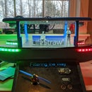
Introduction: DIY Arduino Christmas Clock
Merry Christmas! I was recently approached by Elegoo to create a Christmas themed project with their Arduino R3 Most Complete Starter Kit. With the included components in their kit I was able to create this Christmas themed clock that displays the time and date and every fifteen minutes the tree on the top rotates and glows green to fill a room with Christmas Spirit. Follow along with my Instructable to see how I made this clock and how you can make one too. If you have any questions be sure to let me know in the comment section and I will try my best to help you out!
Step 1: 3d Designing
I started off this project by designing the clock components in Fusion 360. The first component is the clock base. This part houses all of the electronic boards as well as the 16X2 LCD. To mount the components I used M3 nuts and bolts with spaces designed in the parts to pressure fit the M3 nuts. The clock top comes next and is used to hold the stepper motor that is used to rotate the tree as well as the custom slip ring used to power the LED's. Next of course is the custom slip ring. I wont go into too much detail about this part yet as it is only V1 and I have several design revisions I would like to do to create a more efficient and practical slip ring design. This project was done on a very short time schedule so I had to go ahead and use V1 for this clock. I am planning on redesigning the ring and creating a more detailed Instructable later with the info and parts needed to make your own. Anyway the slip ring is used to then mount to the final part being the tree itself. This is a modified tree from a model found on Thingiverse. This part is printed in vase mode to help allow more light from the LED's to shine through. All files needed are attached below for both the clock and current slip ring design.
Attachments
Step 2: Electronics
The next step is setting up the electronics and mounting them into the 3d printed enclosure. I used Elegoo's Most Complete Arduino Kit for this project as it comes with all of the needed electronic parts as well as many other great components that you can use for creating your own projects. For this project I used the Arduino Uno, RTC module, 16X2 LCD, 3X Green LED, and the Elegoo stepper motor and stepper driver circuit. I wired the LCD using the schematic above. I wired the SDA and SCL pins on the RTC to the SCL and SDA pins on the UNO. I then wired the IN1-4 pins on the motor controller to pins 7-10 on the UNO. For the LEDS I wired them through a 68 ohm resistor to pin 6 on the UNO. After the wiring was tested I disassembled and reassembled the parts into the 3d printed enclosure.
Step 3: Code
I used the Arduino IDE to write the program for this clock. I was able to learn how to use the motor controller and RTC module from the lesson provided by Elegoo. These lessons come with example projects as well as example codes for all of the different components included in the kit. I used the different things I learned throughout the lessons and compiled the code below to display the time to the LCD and control the stepper motor based on the time values.
Attachments
Step 4: Final Product
And we are done! I enjoyed putting together this project and hope you all did too. As I said earlier this project was slightly rushed in order to finish before Christmas. There are a couple things I wish I could have done better like including a piezo buzzer to play music as the tree spins, redesign the case to be more aesthetically pleasing and include more space for added components. But as it is I am proud of the final results and want to thank Elegoo again for sending me the components needed to create this Christmas themed clock. If you want to see more of what I do check out my website www.daily3dprinting.com Thank you and Merry Christmas!


