Introduction: Arduino Guitar Fx Pedal

This is a programmable guitar pedal that utilizes an Arduino uno as the effects processor. This is not an amplifier, so it is necessary to run the output into an actual guitar amp. This pedal is meant for guitar specifically. In theory it could be used for bass or other audio input, but the components of the pedal are chosen to handle the levels of guitars not bass. This project is inspired by the instructable Arduino Guitar Pedal by randofo.
Step 1: Parts Needed


The micro controller used for this project is an Arduino Uno REV 3 or equivalent. The one I used is a Chinese clone. Most materials can be found on the internet or at Radio Shack.
Some tools that you will want to have on hand are a soldering iron, solder, a pair of wire cutters, and a pair of wire strippers.
Parts List:
- (x1) Arduino Uno Rev 3
- (x1) large breadboard or 2 or 3 small breadboards. (It can be easier to fit and wire everything using a larger breadboard)
- (x2) 1/4" stereo audio jack
- (x1) Alkaline 9 volt battery
- (x1) battery snap connector
- (x1) 90 ft solid core UL- recognized hookup wire
- (x1) DPDT stomp switch
- (x1) TL082/TL082CP Wide Dual JFET Input Op Amp (8-Pin DIP)
(x4) 1uF 63v capacitor
(x2) 47uF 16v capacitor
(x1) 100pF 50V 10% Hi-Q Ceramic Disc Capacitor
(x1) 0.082µf 100V Mylar Capacitor
(x1) 5pf 50V Ceramic Disc Capacitor
(x6) 10K Ohm 1/4-Watt Carbon Film Resistor
(x2) 1M Ohm 1/4-Watt Carbon Film Resistor
(x1) 390K Ohm 1/4-Watt Carbon Film Resistor
(x1) 1.5K Ohm 1/4W 5% Carbon Film Resistor
(x1) 510K Ohm 1/4W 5% Carbon Film Resistor
(x1) 330K Ohm 1/4W 5% Carbon Film Resistor
(x1) 4.7K Ohm 1/4-Watt Carbon Film Resistor
(x1) 12K Ohm 1/4-Watt Carbon Film Resistor
(x1) 1.2K Ohm 1/4-Watt Carbon Film Resistor
(x1) 1K Ohm 1/4-Watt Carbon Film Resistor
(x2) 100K Ohm 1/4-Watt Carbon Film Resistor
(x1) 22K Ohm 1/4-Watt Carbon Film Resistor
(x1) 33K Ohm 1/4-Watt Carbon Film Resistor
(x1) 47K Ohm 1/4-Watt Carbon Film Resistor
(x1) 68K Ohm 1/4-Watt Carbon Film Resistor
Step 2: Build the Circuit on the Bread Board


This is the meat of the project. There is little to no soldering required for this step as long as the wire on the resistors are long enough to fit neatly on the bread board. A few of the resistors that i used had wires that were to short so I soldered wire onto it to make it easier to fit on the Bread Board. It is important that you pay careful attention to what resistors and capacitors are used and which way they face. You want the negative and positive ends to wire as they are in the fritzing diagram I attached.
Step 3: Foot Switch

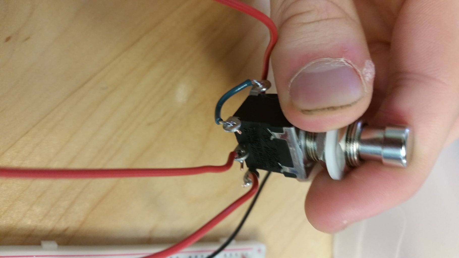
Wire one of the outer pairs of the DPDT stomp switch together.Wire one of the jacks to one of the center pins on the switch. Wire the other jack to the other center pin.Connect a 6" wire to each of the remaining outer pins on the switch.The wire that is in line with the jack on the right should be the input. The wire that is in line with the switch on the left should be the output.
Step 4: Jacks


First connect together the ground tabs on each jack with a short piece of wire.Next, connect the black wire from the battery snap to one of the stereo audio tabs. This is the smaller tab that touches the jack about halfway up the plug.Connect a 6" black wire to the other stereo tab on the other jack.Lastly, connect a 6" red wire to the mono tabs on each of the jacks. This is the large tab that touches the tip of the male mono plug.
Step 5: Code


Copy the code I provide for a distortion sound. You can tweak the code for different effects.

Step 6: Plug in Guitar and Play
After following this tutorial you should have your own programmable effects pedal.