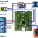
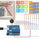
Introduction: Arduino Learner Kit (Open Source)
If you are a beginner in Arduino World and going to learn Arduino having some hands-on experience this Instructables and this Kit is for you. This Kit is also a good choice for the teachers who like to teach Arduino to their students in an easy way.
If you want to learn Arduino you should include the following topics:
Digital Output:
- Controlling multiple LEDs using Arduino
- Generating Tone using Buzzer
Digital Input:
- Interfacing button switch using Arduino
- Interfacing DHT11 Sensor Using Arduino
Analog Input:
- Reading Analog data from a potentiometer
- Interfacing LM35 temperature sensor using Arduino
Analog Output (using PWM):
- Generating multiple colors using the RGB LED.
SPI Communication:
- Interfacing 74HC595 Shift Registerwith Arduino
- Interfacing MAX7219CNG with Arduino for driving DOT Matrix display or multiple seven segment display using only 3 pins of Arduino.
I2C Communication:
- Reading date and time from DS1307 real time clock
UART Communication:
- Interfacing GROVE GPS and Bluetooth Module with Arduino
Display Interfacing:
- Driving 16 X 2 Character LCD display using Arduino
Multiplexing:
- Driving multiple seven segment display using a minimum number of Arduino pins.
You will be wondering to know that the Kit is designed to experiment with all the above-mentioned topics. So, it can be an Ideal Learner Kit for learning Arduino Programming.
[The Kit includes onboard 6 Green LED, 1 RGB LED, 1 Potentiometer, 1 LM35 Sensor, 1 DHT11 Sensor, 4 Button Switch, 4 Seven Segment Display, 1 8X8 Dot Matrix Display, 1 MAX7219CNG IC, 1 74HC595 Shift Register, 1 Buzzer, 1 16X2 LCD display, 1 DS1307 RTC, 3 Grove Universal Connector.]
No more separate shield or module, no more disgusting wiring on the way of learning Arduino.
Watch the demo video:
Step 1: Bill of Materials (BOM)
Following Components will be required for making the Kit:
| Sl. No. | Component Name | Quantity | Where to buy |
| 1. | Arduino Nano | 1 | gearbest.com |
| 2. | 16 X 2 Character LCD | 1 | gearbest.com |
| 3. | 32mm 8 X 8 Single Color Dot Matrix Display | 1 | gearbest.com |
| 4. | 0.56 inch 4 Digit Seven Segment Display (CC) | 1 | aliexpress.com |
| 5. | DHT11 Temperature & Humidity Sensor | 1 | gearbest.com |
| 7. | LM35 Temperature Sensor | 1 | aliexpress.com |
| 8. | 5mm LED | 6 | |
| 9. | 10K Potentiometer | 1 | aliexpress.com |
| 10. | 5K Trim Pot | 1 | |
| 11. | MAX7219 LED Driver IC | 1 | aliexpress.com |
| 12. | 74HC595 Shift Register IC | 1 | aliexpress.com |
| 13. | DS1307 RTC IC | 1 | aliexpress.com |
| 14. | BC547 General Purpose NPN Transistor | 4 | |
| 15. | LM7805 5V Linear Regulator IC | 1 | |
| 16. | 6mm Tactile Button Switch | 4 | |
| 17. | RGB LED (Piranha) Common Anode | 1 | |
| 18. | 5V Piezo Buzzer | 1 | |
| 19. | CR2032 Coin Cell Battery | 1 | |
| 20. | 4 Contact DIP Switch | 1 | |
| 21. | 16 Pin IC Base | 1 | |
| 22. | 8 Pin IC Base | 1 | |
| 23. | 24 Pin IC Base | 1 | |
| 24. | Universal Grove Connector | 3 | |
| 25. | CR2032 Battery Holder | 3 | |
| 26. | Female Pin Header | 4 | |
| 27. | Male Pin Header | 1 | |
| 28. | 220 Ohm Resistor | 20 | |
| 29. | 4.7K Resistor | 6 | |
| 30. | 100 Ohm Resistor | 1 | |
| 31. | 10K Ohm Resistor | 5 | |
| 32. | 4.5 X 5 inch double-sided copper clad board | 1 | gearbest.com |
| Sl. No. | Tools Name | Quantity | Where to buy |
| 1. | Soldering Station | 1 | gearbest.com |
| 2. | Digital Multimeter | 1 | gearbest.com |
| 3. | PCB Claw | 1 | gearbest.com |
| 4. | Wire Cutter | 1 | gearbest.com |
| 5. | Desoldering suction pump | 1 | gearbest.com |
Step 2: Designing Schematic
This is the most important step of making the kit. The complete circuit and board layout were designed using Eagle cad. I make the schematic part by part so that it can be easily understandable and you can modify it easily according to your requirement.
In this section, I will explain each portion separately.
LCD Connection
In this section, I will explain how to connect an LCD (Liquid Crystal Display) to the Arduino board. LCDs like these are very popular and broadly used in electronics projects as they are good for displaying information like sensors data from your project, and also they are very cheap.

It has 16 pins and the first one from left to right is the Ground pin. The second pin is the VCC which we connect the 5 volts pin on the Arduino Board. Next is the Vo pin on which we can attach a potentiometer for controlling the contrast of the display.
Next, The RS pin or register select pin is used for selecting whether we will send commands or data to the LCD. For example, if the RS pin is set on low state or zero volts, then we are sending commands to the LCD like: set the cursor to a specific location, clear the display, turn off the display and so on. And when RS pin is set on High state or 5 volts we are sending data or characters to the LCD.
Next comes the R / W pin which selects the mode whether we will read or write to the LCD. Here the write mode is obvious and it is used for writing or sending commands and data to the LCD. The read mode is used by the LCD itself when executing the program which we don’t have a need to discuss it in this tutorial.
Next is the E pin which enables the writing to the registers, or the next 8 data pins from D0 to D7. So through this pins we are sending the 8 bits data when we are writing to the registers or for example if we want to see the latter uppercase A on the display we will send 0100 0001 to the registers according to the ASCII table.
And the last two pins A and K, or anode and cathode are for the LED backlight. After all, we don’t have to worry much about how the LCD works, as the Liquid Crystal Library takes care for almost everything. From the Arduino’s official website you can find and see the functions of the library which enable easy use of the LCD. We can use the Library in 4 or 8-bit mode. In this kit, we will use it in 4-bit mode, or we will just use 4 of the 8 data pins.
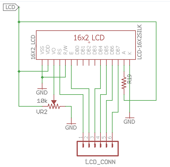
So, from the above explanation, the circuit connection is obvious. The label LCD came from an enable switch through which the LCD can be enabled or disabled. Anode pin is connected through a 220ohm resistor to protect the backlight led from burning. Variable voltage is provided to VO pin of the LCD through a 10K potentiometer. R/W pin is connected to Ground as we only write to the LCD. For displaying data from Arduino we need to connect RS, E, DB4-DB7 pins to Arduino hance these pins are connected to a 6 pin connector.
Seven Segment Display Connection
A Seven-segment display (SSD), or seven-segment indicator, is a form of an electronic display device for displaying decimal numerals that is an alternative to the more complex dot matrix displays. Seven-segment displays are widely used in digital clocks, electronic meters, basic calculators, and other electronic devices that display numerical information.
In this Kit I used 4 digit 7 segment display and multiplexing technique will be used for controlling the display. A 4-digit 7-segment LED display has 12 pins. 8 of the pins are for the 8 LEDs on each of the 7 segment displays, which includes A-G and DP (decimal point). The other 4 pins represent each of the 4 digits from D1-D4.
 Each segment in the display module is multiplexed, meaning it shares the same anode connection points. And each of the four digits in the module have their own common cathode connection point. This allows each digit to be turned on or off independently. Also, this multiplexing technique turns the massive amount of microcontroller pins necessary to control a display into just eleven or twelve (in place of thirty-two)!
What multiplexing does is simple – show one digit at a time on a display unit and switch between display units very fast. Due to persistence of vision, human eye can not differentiate between which display is ON/OFF. The human eye just visualizes all the 4 display units to be ON all the time. Let’s say we need to show 1234. First we turn on the segments relevant to “1” and turn on the 1st display unit. Then we send signals to show “2”, turn off 1st display unit and turn on 2nd display unit. We repeat this process for next two numbers and switching between display units should be done very fast (about within one second delay). As our eyes can’t pick a change occurring repeatedly to any object within 1 second, what we see is 1234 appearing on the display at the same time.
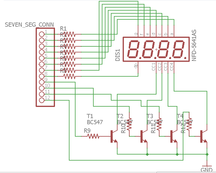
So, by connecting digits common cathodes to ground we are controlling which digit shall be turned on. Each Arduino pin can drain(receive) maximum 40 mA current. If all one digits segments are on, we are having 20×8= 160 mA that is to much, so we can’t to connect common cathodes directly to Arduino ports. Therefore I have used BC547 NPN transistors as switches. The transistor is on, when a positive voltage is applied at the base. To limit the current I used a 4.7K resistor to the base of the transistor.
DS1307 RTC Connection
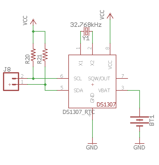
As its name suggests, a real-time clock is used to keep record off time and to display time. It is used in many digital electronic devices like computers, electronics watches, date loggers and situation where you need to keep track of time. one of the great benefits of a real-time clock is that it also keeps record of time even if power supply is not available. Now the question is how can an electronics device like real-time clock work without use of power supply. Because it have small power cell of about 3-5 volt inside which can work for years. Because real time clock consumes a minimum amount of power. There are many dedicated integrated circuits are available in the market which is used to make real-time clock by adding necessary electronic components. But in the Kit I used DS1307 real time clock IC.
DS1307 is IC for real-time clock which is used to count seconds, minutes, hours, days, months any years. Arduino read values of time and date from DS1307 using I2C communication protocol. It also have feature to keep record of exact time in case of power failure. It is an 8 bit IC. It is used to make real-time clock using some other electronic components. Pin configuration of DS1307 is given below:
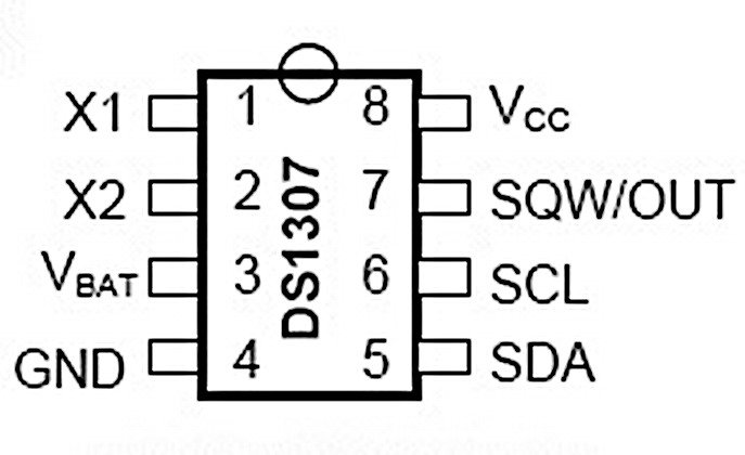
Pin number one and two (X1, X2) is used for crystal oscillator. Crystal oscillator value usually used with DS1307 is 32.768k Hz. Pin three is used for back up battery. Its value should be between 3-5 volt. voltage more than 5 volts may burn DS1307 permanently. Generally, coin cell battery is used to keep track of time in case of power failure to DS1307. After getting power DS1307 shows correct time due to back up battery. Pin 4 and 8 is for power supply. Pin 5 and 6 is used to communicate with other devices with the help of I2C communication protocol. Pin 5 is serial data pin (SDA) and pin 6 is serial clock (SCL). Both pins are open drain and require an external pull-up resistor. If you don’t know about I2C communication, i recommend you to learn about it. Pin 7 SWQ/OUT Square Wave/Output Driver. When enabled, the SQWE bit set to 1, the SQW/OUT pin outputs one of four square-wave frequencies (1Hz, 4kHz, 8kHz, 32kHz). The SQW/OUT pin is open drain and requires an external pull-up resistor. SQW/OUT operates with either VCC or VBAT applied. An LED and 220 ohm resistor in series tied to VCC will produce a 1 HZ blink. This is a good way to tell if the clock chip is working.
74HC595 Shift Register Connection
The 74HC595 is useful if you find yourself needing more outputs than you have available on your microcontroller; Its time to think about using a serial shift register such as this chip.
Using a few of your existing microcontroller outputs you can add multiple 595's to extend outputs in multiples of 8; 8 outputs per 595. When you add more 595s you don't use up any more of your existing microcontroller output pins.
The 74HC595 is a serial-to-parallel shift register or SIPO (Serial In Parallel Out) device for increasing the number of outputs from your microcontroller. Its simply a memory device that sequentially stores each bit of data passed to it.
You send it data by presenting a data bit at the data input and supplying a clock signal to the clock input. At each clock signal the data is passed along a chain of d-types - the output of each d-type feeds into the input of the next.

To start with 74HC595, pins 16 (VCC) and 10 (SRCLR) should be connected to 5V and pins 8 (GND) and 13 (OE) should be connected to ground. This should keep the IC into the normal working mode. Pin 11, 12, and 14 should be connected to three digital pins of the Arduino for transferring data to the IC from the Arduino.
Dot Matrix and MAX7219CNG Connection
A Dot Matrix is a two dimensional patterned LED array, which is used to represent characters, symbols, and images. Almost all the modern display technologies make use of dot matrices including cell phones, television etc. If you're a person who loves playing around with LEDs, dot matrix display is for you.
A typical 8x8 Dot Matrix unit has 64 LEDs arranged in a plane. You can get your hands on two types of Dot Matrices. One which comes as a plain single matrix which has 16 pins to control the rows and columns of the array. This one would use a lot of wires and things can get a lot messier.
To simplify these things, it is also available integrated with MAX7219 Driver, which has 24 pins. At the end you have 5 pins to connect to your I/O which makes your job a lot more easier. There are 16 output lines from the 7219 driving 64 individual LEDs. Persistence of vision is exploited to make the LEDs appear to be on all the time when in fact they are not. You can also control the brightness of the LEDs through the code.
This small IC is a 16 bit serial shift register. The first 8 bits specify a command and the remaining 8 bits are used to specify the data for the command. In a nutshell, the working of the MAX7219 can be summarized as follows:
We know that our eyes remember a flash for about 20ms. So the Driver flashes the LEDs at a rate greater than 20ms which makes us feel that the light never goes off. In this way, the 16 pins control 64 LEDs.
 The VCC and GND of the module go to the 5V and GND pins of the Arduino and the three other pins, DIN, CLK and CS go to any digital pin of the Arduino board. If we want to connect more than one module we just connect the output pins of the previous breakout board to the input pins of the new module. Actually these pins are all the same except that the DOUT pin of the previous board goes to the DIN pin of the new board.
Attachments
Step 3: Designing Board Layout (PCB)
If you want to make your design more appealing, then PCBs are the next step. With the help of PCBs, we can avoid common problems like noise, distortion, imperfect contact, etc. Moreover, if you want to go commercial with your design, you have to use a proper circuit board.
But, many people, especially beginners, will find it difficult to design circuit boards as they feel it as a tedious job and requires extreme knowledge in circuit board design. Designing printed circuit boards is actually simple (yes, it does need some practice and efforts).
Note that the Schematic's job is only to define the parts and the connections between them. Only in Board layout does it matter where the parts physically go. On Schematics, parts are laid out where they make sense electrically, on Boards, they are laid out where they physically make sense, thus a resistor that is right next to a part in the Schematic may end up as far away from that part as possible in the Board.
Typically, when you lay out a board, you first place the parts that have set locations that they need to go, like connectors. Then, group up all parts that logically make sense together, and move these clusters so that they create the smallest amount of crossed unrouted lines. From that point, expand those clusters, moving all of the parts far enough apart that they don't break any design rules and have a minimum of unrouted traces crossing.
One thing with printed circuit boards is that they have two sides. However, you typically pay per layer that you use, and if you are making this board at home, you might only be able to reliably make one-sided boards. Due to the logistics of soldering through-hole parts, this means that we want to use the bottom of the PCB.Use the Mirror command and click on the surface-mount parts to switch them to the bottom layer. You may need to use the Rotate or Move command to correct the orientation of the parts. Once you have all of the parts laid out, run the Ratsnest command. Ratsnest recalculates the shortest path for all of the unrouted wires (airwires), which should clear up the clutter on the screen by a fair amount.
After designing the PCB, you need to print the design. Though lots of tutorials are available on the Internet making a good quality PCB by hand is a big challenge. The PCB used in this project is printed from JLCPCB. The print quality is very good. I received 12 boards, all nicely vacuum sealed and bubble wrapped. all looks good, precise tolerances on solder mask, clear character on silk screen. I added the Graber file and you can directly send it to JLCPCB to get good quality printed PCB.

JLCPCB manufactures 5pcs of PCBs with maximum size 10cmx10cm in just 2 dollars. This is the cheapest price we have ever seen. The shipping charge is also low as compared to other companies.
For ordering visit the JLCPCB website. The home page displays a quotation calculator that takes you to the ordering page. On the quotation calculator, simply enter the size of the PCB, quantity, layers and thickness.
The quote page has an excellent default setting for beginners who do not understand all the PCB manufacturing terms and standards. For example, the terms like Surface Finish, Gold Fingers, Material details, etc. can be confusing for hobbyists, so, you can just avoid those settings. The default setting is all good. If you want to know the meaning of those terms and want to figure out what’s their significance on your PCBs, you can simply click on the question mark right above the terms.
For example, JLCPCB has well explained the term Gold Fingers, Material details, etc. If you are a beginner, you just need to set the PCB dimensions, layers, color, thickness and the quantity you need. Other default settings can be kept as they are.
You can know more from this instructable.
Step 4: Soldering (Resistor, Pin Header & IC Base)
Soldering is one of the most fundamental skills needed to dabble in the world of electronics. The two go together like peas and carrots. And, although it is possible to learn about and build electronics without needing to pick up a soldering iron, you’ll soon discover that a whole new world is opened with this one simple skill. Soldering is the only permanent way to ‘fix’ components to a circuit. And basic soldering is easy. All you need is a soldering iron and some solder. When my dad taught me as a teenager, I remember picking it up quite fast.
Before starting the soldering you need some preparation for good soldering.
Clean the tip
When the iron hot, start with cleaning the tip to remove old solder from it. You can use a wet sponge, a copper scouring pad or something similar.
Tinning the tip
Before you start soldering, you should tin the tip of the soldering iron. This makes the tip transfer heat faster and thereby making the soldering easier and faster. If you get any droplets of tin on your tip, use a sponge, a copper scouring pad or just shake it off.
A clean surface is very important if you want a strong, low resistance solder joint. All surfaces to be soldered should be cleaned well. 3M Scotch Brite pads purchased from the home improvement, industrial supply store or automotive body shop are a good choice as they will quickly remove surface tarnish but will not abrade the PCB material. Note that you will want industrial pads and not the kitchen cleaning pads impregnated with cleaner/soap. If you have particularly tough deposits on your board, then a fine grade of steel wool is acceptable but be very cautious on boards with tight tolerances as the fine steel shavings can lodge between pads and in holes. Once you have cleaned the board down to shiny copper you can use a solvent such as acetone to clean any bits of the cleaning pad that may remain and to remove chemical contamination from the surface of the board. Methyl hydrate is another good solvent and a bit less stinky then acetone. Be aware that both these solvents can remove ink, so if your board is silk screened, test the chemicals first before hosing down the entire board.
I hope you completed all the formalities above and ready to place the components on the PCB. The kit is designed for through-hole components and through-hole components on a PCB starts by placing the part in its hole.
After the component and board have been cleaned, you are ready to place the components onto the board. Unless your circuit is simple and only contains a few components, you will probably not be placing all the components onto the board and soldering them at once. Most likely you will be soldering a few components at a time before turning the board over and placing more. In general, it is best to start with the smallest and flattest components (resistors, ICs, signal diodes, etc.) and then work up to the larger components (capacitors, power transistors, transformers) after the small parts are done. This keeps the board relatively flat, making it more stable during soldering. It is also best to save sensitive components (MOSFETs, non-socketed ICs) until the end to lessen the chance of damaging them during assembly of the rest of the circuit. Bend the leads as necessary and insert the component through the proper holes on the board. To hold the part in place while you are soldering, you may want to bend the leads on the bottom of the board at a 45-degree angle. This works well for parts with long leads such as resistors. Components with short leads such as IC sockets can be held in place with a little masking tape or you can bend the leads down to clamp onto the PC board pads.
Apply a very small amount of solder to the tip of the iron. This helps conduct the heat to the component and board, but it is not the solder that will make up the joint. To heat the joint you will lay the tip of the iron so that it rests against both the component lead and the board. It is critical that you heat the lead and the board, otherwise the solder will simply pool and refuse to stick to the unheated item. The small amount of solder you applied to the tip before heating the joint will help make contact between the board and the lead. It normally takes a second or two to get the joint hot enough to solder, but larger components and thicker pads/traces will absorb more heat and can increase this time.If you see the area under the pad starting to bubble, stop heating and remove the soldering iron because you are overheating the pad and it is in danger of lifting. Let it cool, then carefully heat it again for much less time.
Always make sure that you apply enough heat, otherwise, you might end up with a “cold solder joint”. Such a solder joint might look okay without actually providing the connection you want. This can lead to some serious frustration when your circuit doesn’t work and you are trying to figure out why ;) When you look at a cold solder joint up close, you’ll see that it has a small gap between the solder and the pin.
If you are happy with your soldering, cut off the component lead from above the solder joint.
At the time of soldering, I followed all the above tips. I first placed all the resistors onto the board and soldered. Then I placed IC base for all the IC and soldered carefully. For soldering IC’s, it is smart to use an IC socket. Some ICs will break if the heat from the soldering iron is too hot. Then I soldered Battery case, Grove connectors and pin headers.
To know more about placing and soldering PCB component you may read this nice instructable:https://www.instructables.com/id/Simple-PCB-soldering/
Step 5: Soldering (LED & Switch)
After soldering all the resistors, pin headers and IC base it is the right time to solder LED and switches. The kit contains six 5mm LEDs and all are placed in a single line. Then I placed 4 tactile button switch.
Solder small parts first. Solder resistors, jumper leads, diodes and any other small parts before you solder larger parts like capacitors and transistors. This makes assembly much easier. Install sensitive components last. Install CMOS ICs, MOSFETs and other static sensitive components last to avoid damaging them during assembly of other parts.
While soldering is not generally a hazardous activity, there are a few things to keep in mind. The first and most obvious is that it involves high temperatures. Soldering irons are going to be 350F or higher, and will cause burns very quickly. Make sure to use a stand to support the iron and keep the cord away high traffic areas. Solder itself can drip, so it makes sense to avoid soldering over exposed body parts. Always work in a well lit area where you have space to lay parts out and move around. Avoid soldering with your face directly above the joint because fumes from the flux and other coatings will irritate your respiratory tract and eyes. Most solders contain lead, so you should avoid touching your face while working with solder and always wash your hands before eating.
Step 6: Soldering (Seven Segment, LCD & Dot Matric)
This is the last stage of the soldering. In this stage, we will solder three big components (seven segment display, dot matrix display and the LCD display). First, I soldered seven segment display to the board because it is the smallest in size and less sensitive. Then I placed the dot matrix display. After soldering the dot matrix display I placed the last component, the LCD display to the board. Before placing the LCD to the board I first soldered male pin header to the LCD and then placed to the main PCB board. The soldering job is done with soldering of LCD.
After you have made all the solder joints, it is good practice to clean all the excess flux residue from the board. Some fluxes are hydroscopic (they absorb water) and can slowly absorb enough water to become slightly conductive. This can be a significant issue in a hostile environment such as an automotive application. Most fluxes will clean up easily using methyl hydrate and a rag but some will require a stronger solvent. Use the appropriate solvent to remove the flux, then blow the board dry with compressed air.
Step 7: The Complete Kit
I hope you completed all the above steps. Congratulation! You have made your own Arduino Nano Learner Kit. Now you can explore the world of Arduino very easily. You don't need to buy different shield or module to learn Arduino Programming. The Kit includes all the basic stuff required for a learner.
You can build the following projects using the kit very easily. No extra device or component is required. Even the board requires very few simple jumper connection.
- You can make a thermometer using LM35 and seven segment display
- You can make temperature and humidity meter using DHT11 and LCD display
- You can make a simple piano using buttons and buzzer
- You can make a digital clock using RTC and LCD/Seven Segment. You can also add alarm using Buzzer. Four buttons can be used for time adjusting and configuration.
- You can make an analog clock using RTC and Dot matrix display
- You can make a game using buttons and Dot matrix display.
- You can connect any Grove module like Grove Bluetooth, different Grove Sensor, etc.
I mentioned only a few possible options. You can create much more stuff using the kit. In the next step, I will show you some example using the Kit with the Arduino sketch.


