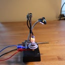
Introduction: Arduino Lego Photocell.
This instructable shows how to join the worlds of Lego Technics, PC and Arduino.
Driving a Lego motor with an Arduino board and a relay is not very dificult. But if you want to experiment with more advanced automation challenges you need a photocell to detect the position of an actuator or to count revolutions.
This demo shows how to build your photocell using only a LED, a 1K resistor and one PT334 phototransistor.
Another interesting aspect of this demo is how to access Arduino variables real-time from the PC just like you would do with a PLC. WawiLib-PC is used to read and write the Arduino variables that control the Lego setup.
Supplies
- LED (blue)
- resistor 1K
- 4 Dupont breadboard wires
- 8 cm heatshrink
- soldering tools
- WawiLib-PC software
- Lego Technics building blocks
- Arduino Uno or Mega
Step 1: Assembly of LED Light Source With Series Resistor.
This movie shows how to connect a LED, a 1K resistor and 2 Dupont wires.
One side of the LED is connected to a Dupont wire.
The other side of the LED is connected to a 1K resistor.
The resistor is then connected to a second Dupont wire.
Dupont wires have plugs compatible with Arduino headers.
The resistor and the live wires are insulated with heat shrink to prevent shortcuts.
Step 2: Assembly of PT 334 Sensor.
A PT334 is a very cheap sensor that acts as a phototransistor.
Phototransistors use light instead of electrical current to switch.
The assembly of sensor is very similar to the assembly of the LED light source.
The nice thing about the PT334 is that it is electrically compatible with the Arduino I/O's.
Step 3: Assembly of Photocell.
Using a small drill you can make the LED and the PT334 fit exactly in the holes of a Lego Technics building block.
They both have similar form factors. (Be very careful with the drill as it can cause injuries. The movie is 2x speeded up.)
Step 4: Arduino Coding.
The source code contains code to link the variable photoCellOn with digital output 3. Output 3 feeds the LED in the photocell. ObjectDetected reflects the state of digital input 2. Input 2 is connected to the PT334.
Do note that digital input 2 is initialized as INPUT_PULLUP so the PT334 can function as an open-collector device. This means that once the PT334 is lit, it will drain current from its collector to its emitter. This will cause voltage drop over the pull-up resistor in the Arduino. Due to the voltage drop, the input of the Arduino will see a low voltage. This effect creates a logic '0' state on the digital input of the Arduino processor.
#include <WawiSerialUsb.h>
WawiSerialUsb WawiSrv;
bool photoCellOn;
bool objectDetected;
void wawiVarDef()
{
  WawiSrv.wawiVar(photoCellOn);
  WawiSrv.wawiVar(objectDetected);
}
void setup()
{
Serial.begin(115200);
WawiSrv.begin(wawiVarDef,Serial,"My Arduino");
pinMode(2,INPUT_PULLUP);
pinMode(3,OUTPUT);
}void loop()
{
digitalWrite(3,photoCellOn);
objectDetected=digitalRead(2);
WawiSrv.loop();
}Attachments
Step 5: Final Demonstration.
This movie contains 2 parts:
1) The simple demo where an Arduino UNO activates an output connected to the photocell LED and shows the status of the sensor (covered or not).
2) A more advanced demo where the Lego motor controls a rotating Lego bar.
The position of the Lego bar is reflected in a variable rotActual. When it turns forward 1/2 revolution, the value of rotActual is incremented. When the bar turns backwards 1/2 turn the value of rotActual is decremented. The Lego photocell triggers the increment or decrement of rotActual.
There is a value rotSetpoint where the user introduces the target value of the rotating bar.
The variable machineStatus contains a string with the actual status of the machine (on/off etc...).
The Arduino Mega controls 4 relays feeding the Lego motor; Rotating backwards is done by inverting the polarity of the Lego motor connections using 2 of the 4 relays.
The motor controls the rotating bar via the Lego gear box so the bar follows the target value in rotSetpoint just like a simple servo.
WawiLib-PC is used to read and write the values of the Arduino variables using the Arduino USB programming port. For additional info about WawiLib-PC: www.SylvesterSolutions.com


