Introduction: Arduino Light Level Gauge

This simple tutorial requires an Arduino UNO with the Arduino IDE and a PC with the components seen below.
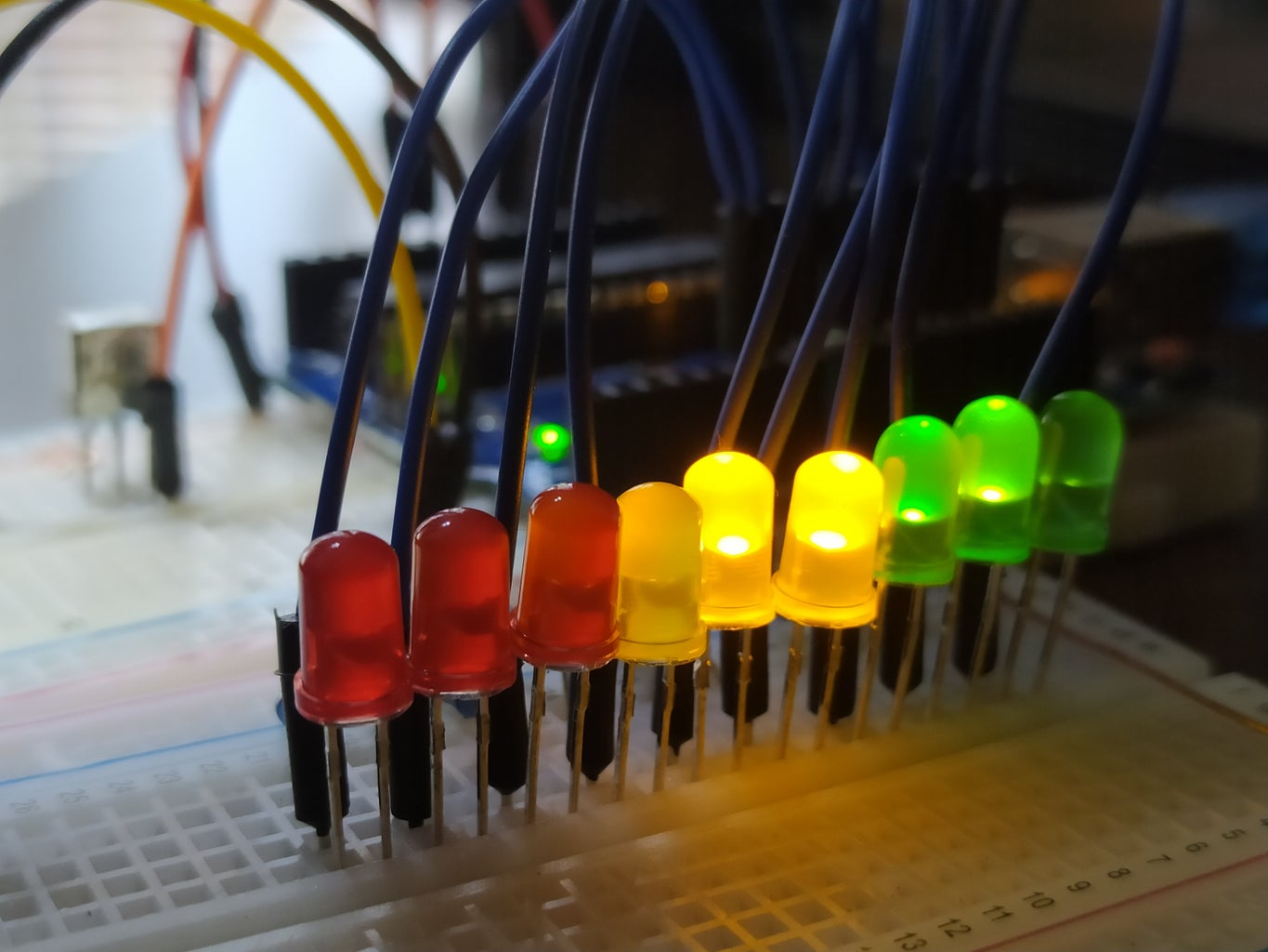
The end result would be a simple "light gauge" sensor. That is, as the light intensity increases, the LEDs will light up from green to amber and to red. Thus demonstrating the intensity of the light hitting the LDR Sensor.
Supplies
- 3x green led
- 3x amber led
- 3x red led
- 10x 100k resistors
- 1x LDR Analogue Sensor
- 1X Arduino Uno
Step 1: Schematic
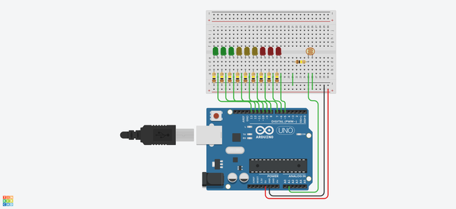
Attached is a simple schematic of the Light Gauge.
Note how from pin 5 to 13 starting from red and working our way through to green, we have neatly constructed a layout that looks similar to any gauge or level indicator.
The board is powered with the 5v pin and the ground is set securely on the Arduino.
How to set up an LED:
Most LEDs have a long pin and short pin. One thing to remember is that the short pin connects directly to the ground through a resistor. This is so that we don't accidentally blow it. The short pin connects directly to an Arduino pin of your choosing.
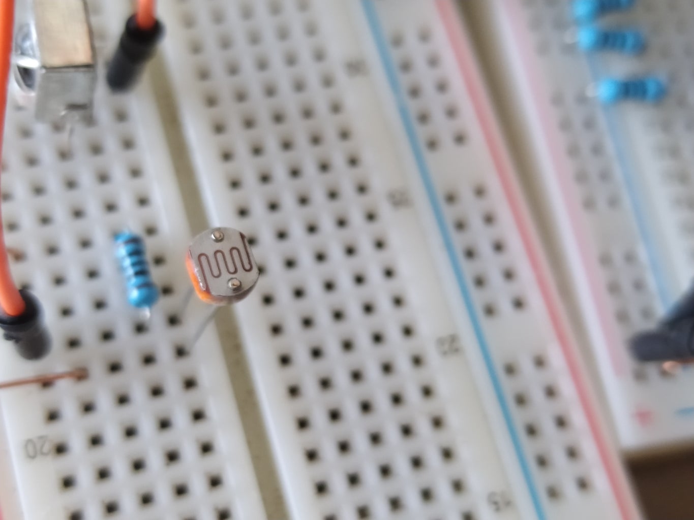
How to set up the LDR:
Make sure that one pin on the LDR goes from the ground, through a resistor and then only to the LDR. The other pin on the LDR then needs to connect to positive and to the Arduino pin of your choosing.
Look closely at the schematic to make sense of how the layout is done. Each LED is hooked up with a 100k resistor and subsequently to pin 5 to 13 on the Arduino.
The LDR is connected to pin A1 on the board and also has a 100k resistor.
Step 2: Code, Setting Up Our Pins
The code I have provided makes use of simple algorithms to ensure the relevant pins are all associated with the correct LEDs and the sensor.
First create an array of our LED pins 13 to 5:
int ledPins[9] = {13, 12, 11, 10, 9, 8, 7, 6, 5};
Then assign the light sensor and set a sensor variable to 0:
int lightSensor = A1;
int sensorValue = 0;
Now we can use our setup method to assign each pin as an output, and allow the Sensor to send information:
void setup() {
/* LED */ for (int i = 0; i <= 9; i++) { pinMode(ledPins[i], OUTPUT); }
/* SENSOR */ Serial.begin(9600); }
Step 3: Simple Functions
We will first create a function that lets us flash an led for a set delay:
void ledFlash(int pin, int d) {
digitalWrite(pin, HIGH); delay(d); digitalWrite(pin, LOW); delay(d); }
Finally, another function that uses a simple algorithm to decide how many of the LEDs will be on and off depending on its input:
void ledRange(int num) {
for (int i = 0; i <= num; i++) { digitalWrite(ledPins[i], HIGH); } for (int i = num; i <= 9; i++) { digitalWrite(ledPins[i], LOW); } }
Step 4: Loop
Now we can make use of the loop method that deals with the values our sensor sends to us, and decides what LEDs will light up depending on the intensity of the light source:
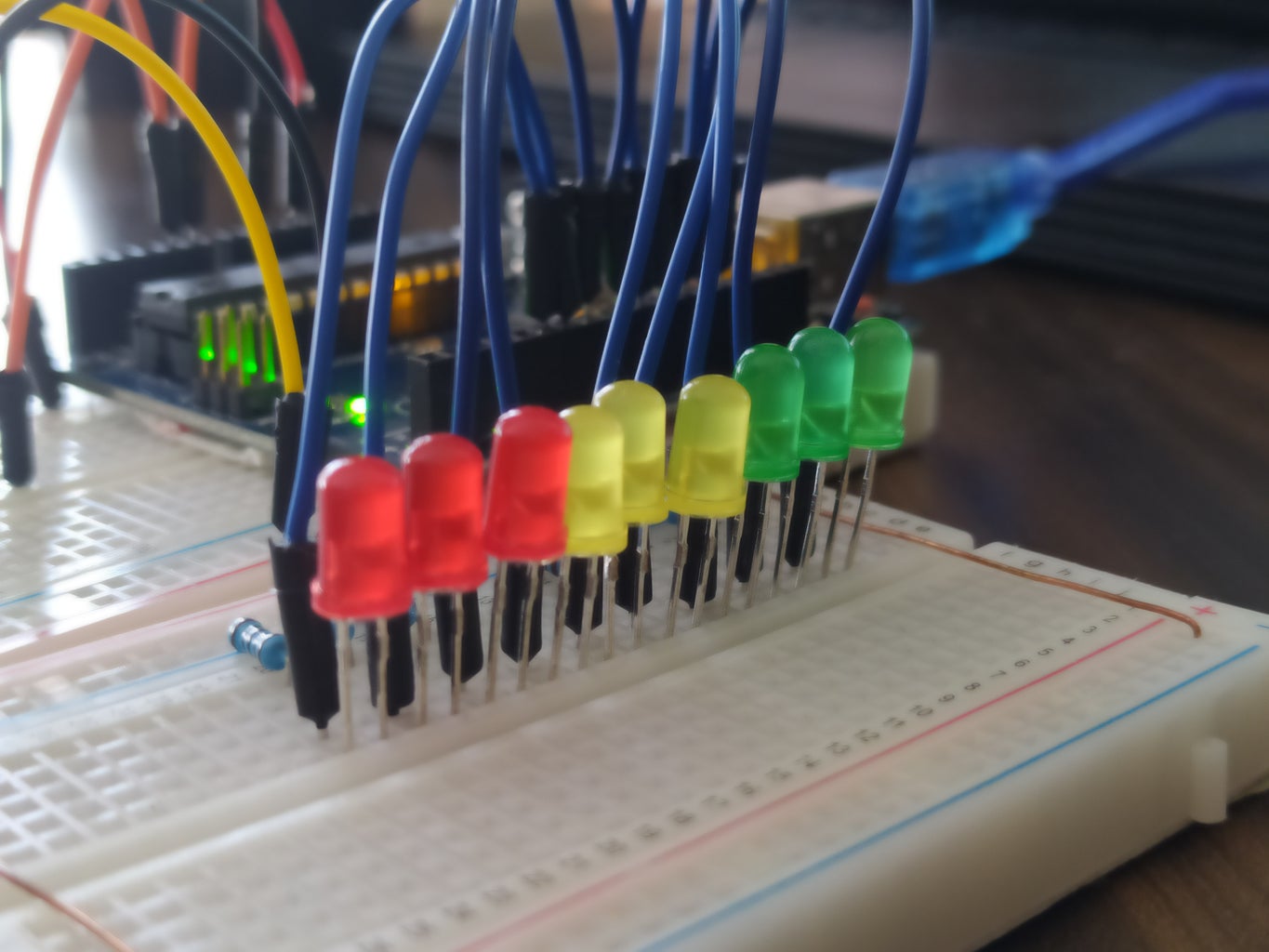
You can see the initial logic has the first green LED flash, letting us know that the Arduino is running, but there is not enough light input for the gauge to start responding.
void loop() {
sensorValue = round(analogRead(lightSensor)); // sensorValue = ((sensorValue + 10 / 2) / 10) * 10; Serial.println(sensorValue);
if (sensorValue < 100) { ledFlash(13, 500); } else if (sensorValue >= 100 & sensorValue < 130) { ledRange(1); } else if (sensorValue >= 130 & sensorValue < 160) { ledRange(2); } else if (sensorValue >= 160 & sensorValue < 190) { ledRange(3); } else if (sensorValue >= 190 & sensorValue < 220) { ledRange(4); } else if (sensorValue >= 220 & sensorValue < 250) { ledRange(5); } else if (sensorValue >= 250 & sensorValue < 280) { ledRange(6); } else if (sensorValue >= 280 & sensorValue < 310) { ledRange(7); } else if (sensorValue >= 310 & sensorValue < 340) { ledRange(8); } else if (sensorValue >= 340) { ledRange(9); } }
You can see there is a simple method to round off the sensor value to the nearest 10. This is optional, and dependant on the LDR sensors' quality.
Step 5: Send It Up to the Arduino
Now that the code is up and running, we can see that if there is no light source, the green light simply flashes.
The moment we introduce a light source, the LEDs all light up in their relevant order.
Attached is the Arduino code for you to use.


