Introduction: Arduino Light Theremin in Your House

Remaking Arduino Light Theremin from https://www.instructables.com/id/Arduino-Light-Th...
A theremin is an electronic music device that can sense the position of a performer‘s hands and create musical sounds all without the performer ever touching the device. For our light theremin, we are going to adapt this concept and create a theremin that controls color instead of music.
Things you will need:
Arduino
Computer
LED's
Photoresistor
Resistors
Box
Step 1: Prepare to Light Up!
Let's begin by grabbing 7 LED's out of our kit. You can add more if you'd like, just make sure you add an extra resistor and wire to an open Arduino pin. Keep in mind that the Arduino can not supply a lot of power, so at a certain point, adding more LED's just makes them all dimmer.
Ground Wire/ Add LEDs
Start by adding a wire between the ground (negative "-" ) rail of the breadboard and the GND pin of the Arduino. This makes sure that all the components on the Arduino and breadboard now share a common ground and can make a complete circuit. Next, plug the short leg (ground) of the LED into the ground (negative) rail of the breadboard
Add Resistors & Wires
Your going to need 7 resistors, I've chosen to use the 82 Ohm (grey, red, black), because the LED's will be bright enough to see but not draw to much power from the Arduino.
Step 2: Photoresistor Circuit
To make the photoresistor circuit we are again going to create a voltage divider. Grab your photoresistor and an 82 Ohm resistor (grey, red, black). Place one leg of the photoresistor into the ground rail of the breadboard and the other leg in any row of the breadboard.
Next, add a wire from the 5V output on the Arduino to a different row on your breadboard and have the 10K Ohm resistor bridge the 5V power row and photoresistor row.
Finally, now that we have made a voltage divider we need to get the signal from the divider to the Arduino, so take another wire and plug one end into the photoresistor and 10K resistor row and the other end into A0 (analog pin 0) on the Arduino.
Step 3: Coding Part 1


My code is here! https://create.arduino.cc/editor/cntsurvi/910d5a5f...
To code the light theremin we are going to expand on the previous analog sensor lesson, and take it a step further by having one sensor trigger multiple LED actions. First, download the attached LED.ino and open it up in the Arduino IDE. To begin we need to initialize all 7 LEDs. I kept the naming conventions fairly standard here, but you can label the LED's according to any convention you prefer.
Now that each LED is named we need to set up our inputs and outputs
Note that we are also starting a serial port connection so we can calibrate the device later on. The 9600 value is the speed at which the computer and Arduino talk to each other. This is called Baud Rate, and you can read more about it in the additional resources section.
Step 4: Coding Part 2

Building off our analog sensor code, we are going to utilize the same LED function but we need to expand on it a little bit to be able to accommodate for the larger amount of LEDs. To do this we want to increase the number of function parameters and make sure we trigger the extra pins.
In this LED State function, we have parameters w1, w2, w3, w4, w5, w5, w6, and w7. Setting these to either HIGH or LOW in the main loop with turn on or off these LED's.
Step 5: Coding Part 3

Let's get to the real meat of this code and dive into the main loop. We know we want different LED's to light up in accordance with the distance away your hand is from the sensor. This means that more LEDs should light up when less light is hitting the sensor (as your hand covers it up). As we saw in previous lessons the ADC value of the photoresistor circuit increases with a decrease in light, so we want to structure our code in a way light lights up more LEDs as the ADC value increases.
Whew, that was a brain bender! Let's take a look at the code to help us understand what we need
Ahhhh, now this makes more sense. We are constantly checking the value of the photoPin and then light up more and more LED's the higher that value gets. As you'll see in the video on the next step, these default values worked pretty well for me with the ambient light in the room, but you may have to play around with these values somewhat to get them reacting to the distance of your hand in the way you want.
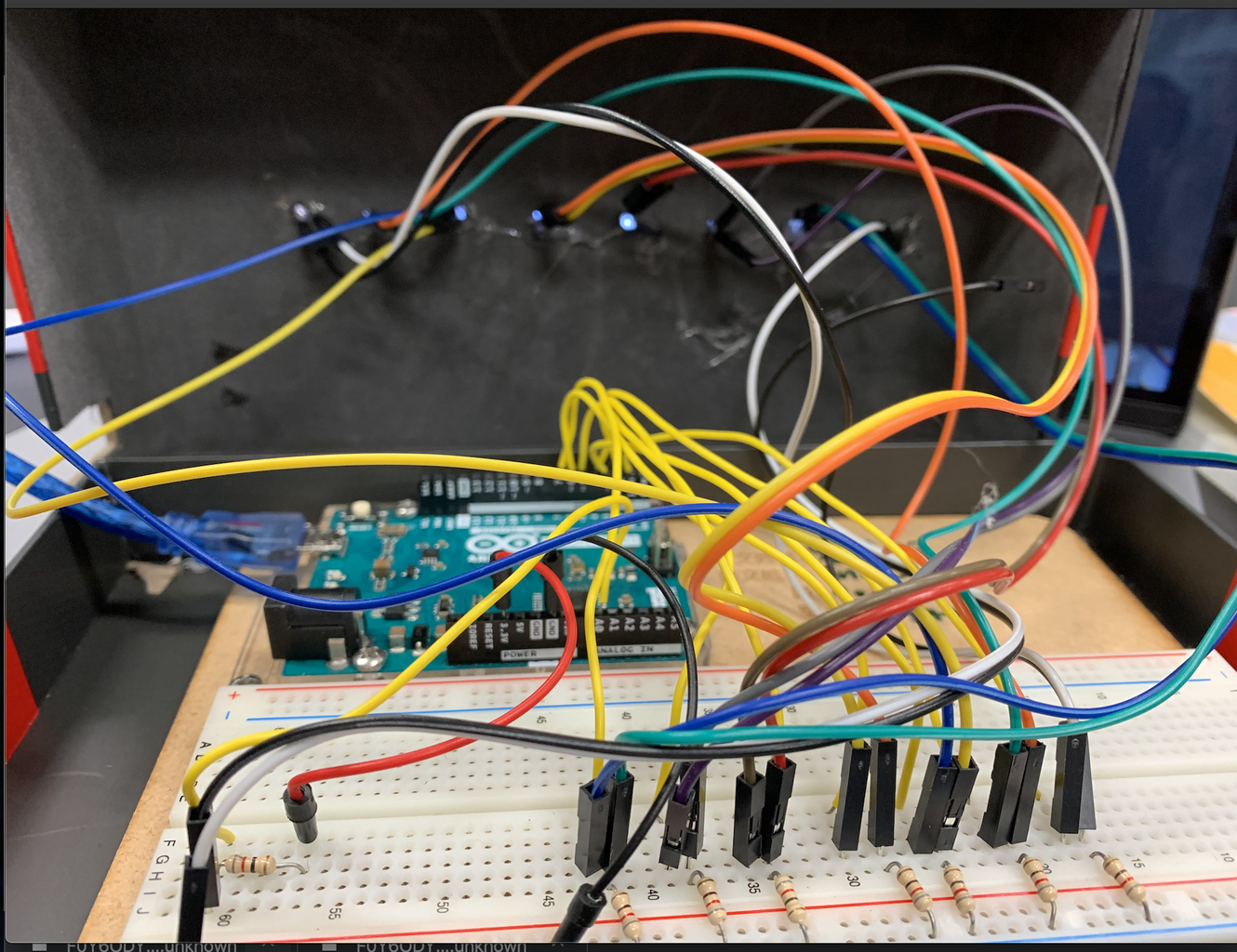
Step 6: Bread Board Test
Let's upload the code to the Arduino and play with our new Theremin.
Step 7: Making Theremin Enclosure/Theremin Wiring Part
The main body of the theremin is a paper box. I then proceeded to cut 7 slits, spaced it apart, with a knife and scissor. Then I test fit the LED's.
Connect your orginal wire with another one to make it long enough to plug into the hole you just made.


Step 8: Light Theremin
Now that it's all wired up let's try out our new Light Theremin :)


