Introduction: Basic Tank-drive Robot Control Over Bluetooth Using Mbed With the Freescale K64F


This Instructable is based on this earlier work that shows how to control a typical tank-drive style robot using Arduino and an Android app, as shown in this RC car for Android Instructable.
I have used this work as a basis for many robots in the past few years like Teo Jansen inspired walking chassis as shown at http://boim.com/Walkin8r/
and a full sized remote control wheelchair,
This Instructable will take the base Arduino code, and port it to work on the Freescale K64F ARM based microcontroller board,using the mbed.org on-line IDE.
The use of this board with the mbed IDE is very similar to other mbed enabled boards.
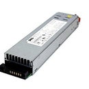
This example uses a 30A DBH-1A controller from wingxine, and a serial-over-Bluetooth module such as the HC-06.
The motor driver code is based off of some slightly simpler code which controls the more common L298N based motor control modules. Comment out the #define DBH1 line in main.cpp to revert to the default L298N logic.
You will need a 4-pin 1-row female 2.54mm spacing header to mount the HC-06 to the K64F board. For the DBH-1x series controllers, you will want a 10-12 pin 2-row female header, whereas the L298N modules usually take a 6-pin 1-row female header.
Step 1: Verify Serial Operation


This step assumes that you have sucessfully used the mbed on-line IDE to compile, download, and run code on your Freescale board. If you have not yet done this, please follow the links in the mbed.htm file on the root folder of your K64F board, and/or review the Instructable on using the FreeScale K64F.
Solder a 4-pin header for the bluetooth module to your K64F board, and install the Bluetooth module.
From the mbed IDE, select the frdm_serial program as modified by Aaron Birenboim and import. This is a significant modification of the delivered frdm_serial example. For unknown reasons, I could not get a simple Serial::getc() call to work with the Bluetooth module. This example shows the interrupt driven ring buffer method which is adopted in the full TankDrive robot control program.
When your Bluetooth module is plugged into the header, and the MCU board is powered by USB from your host computer, you should see a flashing light on the Bluetooth module indicating that it is not yet connected to a Bluetooth host. Check the code in main.cpp to make sure that the baud setting for the BT object is set to the baud rate set on your Bluetooth module. They usually deliver serial-over-Bljuetooth modules with the default rate of 9600 baud. This rate can be increased using an AT command, as discussed in the instructable for the HC-05 Bluetooth module. Note that you do not need an Arduino to do this. If you have a USB-to-Serial converter, it can be wired directly to the HC06 class module to enter AT commands.
You can connect to your bluetooth module with an Android app like BlueTerm.
Open a serial terminal program on your host computer to communicate with the USB-serial connection on the K64F. Under chrome, you can use an app like beagle-term, or the serial monitor on the Arduino IDE, or another serial-terminal program. Be sure to set your baud rate to 115200, or alter the mbed code to match your desired baud rate.
You should be able to type text on BlueTerm, and see the results on your host serial terminal program.
If you plan to use the CXEM car app from the Android RC car control over Bluetooth Instructable, start it up. Enter the MAC address, which should be shown when you connect to the Bluetooth module from BlueTerm. Enter button-control mode and touch a button. You should see several Lxxx and Rxxx commands showing up on your host terminal if communication is working.
Step 2: Import TankDrive Code


From the mbed IDE, select Import, and "click here" to import by URL.
Enter https://developer.mbed.org/users/Mr_What/code/Tank... for the TankDrive program.
Compile and download the image from this code. Upon reset, the program should flash the set of all primary and complimentary primary colors in sequence. If you see this sequence, the code is running.
Review the code for int main() in main.cpp to make sure that Bluetooth communication is set to your speed.
Also verify that you used the same pins called out in the global MotorDrive constructors near the top of main.cpp. If you selected different pins, set their names appropriately in the global constructors for the MotorDrive objects in the preamble of main.cpp.
Many higher power motor control modules, such ad the DBH-1x series, have a max PWM setting. In the case of the DBH-1A this is 98%. I am not sure why. They warn of transistor burn out when run at 100% duty cycle. It could be that they use a charge pump for N-Channel MOSFETS on the high side, and if this charge pump drains, the transistor may not be fully "on", which would cause it to heat up. To be safe, I used PWM pins for the motor driver's direction inputs and put a max PWM rate of 98% on these lines. I control speed primarily with PWM on the EN pin, but using a 98% duty cycle PWM on the direction pins ensures that I meed the recommendations for using the DBH-1x module.
The common L298N chip does not have this limitation. If you are using an L298N module, comment out the #define DBH1 line in the preamble of main.cpp. For the L298N driver, you will not need PWM capable pins for the IN1/IN2 signals. They can be simple digital I/O capable pins. You will also note that the L298N version of this driver has only 3 inputs to the constructor, since there is no current-sense output provided on most L298N modules.
For testing, I wired the motor control signals to a breakout on a breadboard. Each of these signals was attached to an amplified logic probe which illuminates an LED. I fear that you may not be able to drive regular 2v, 20mA LED's reliably from an ARM digital I/O output, especially when they are shared with a 5v TTL input. The construction of these amplified logic indicators may be the subject of a future Instructable. The one shown draws about .3mA from the digital I/O pin, and amplifies this with an NPN Darlington to illuminate the LED from a 5V source. I have since ordered a bag of 2N7000 small-signal MOSFETs for this purpose. They should be able to switch without the need for the current limiting base resistor, and draw almost 0A to drive the light. (A small amount of current is needed to switch state, but once the transistor state is set, current draw drops to nA or less)
If you do not which to build a testing breakout, that is fine. Now that the code is tested, you should be able to test directly on DC motors.
Step 3: Test Using BlueTerm
Wire your K64F to the motor drive module.
Connect to the Bluetooth module using BlueTerm.
Connect a serial terminal to the USB-serial port on the K64F from the host computer to view diagnostics.
For testing you may want to change the Deadman timeout from the default of 250 to 500ms to something more like 15000ms in the initMotorDrive() fuinction of main.cpp. This will allow you to test from a terminal without the remote control app. When running an actual robot, the deadman timeout should be closer to the command rate from your command app, such as CXEM-car, around 100 to 500 ms.
From the Bluetooth terminal, type a command like L255 for full-speed ahead on the left motor. Then L-99 for nearly half-speed reverse. You should note that the motor stops briefly with the electrical brake, then starts up in reverse. You can do similar for the right motor with commands like R-255 then R111. When issuing the commands R0 or L0 the motors should stop quickly using the electrical brake.
The electrical brake in engaged when both directional inputs are low, and the enable is high. Otherwise, when driving the main speed control is accomplished with PWM on the enable line.
Diagnostics describing all of the above actions can be displayed on the PC-USB terminal. If you look through the code there are more diagnostic reports commented out. Most of these diagnostics will have commands that look like DiagSerial.printf(...). You can remove these comments for more diagnostics. I have found that too many diagnostics printouts can cause the MCU to freeze when providing a high-rate command stream, such as the opne produced by the CXEM-car app.
Step 4: Test From Remote-control App
Use of the remote control app is converted in the Instructable on Bluetooth control of an RC car for Android. To summarize:
- Use an app like BlueTerm to pair with the Bluetooth device and get it's MAC address
- Under the CXEM Car menu is a Settings selection where you can enter the MAC address.
- You can then enter a control mode. At this time the app should connect and the serial-over-Bluetooth module should stop blinking
- Commands from the app should now drive the motors
If something does not work, try connecting with Blueterm, or go back to the Testing Serial connection step to make sure that the app is communicating properly.
If the connection freezes, try removing diagnostic printouts from the TankDrive firmware.
If everything is working well, go back to the initMotorDrive() function in TankDrive's main.cpp, and set the deadman timeout to a reasonable value like 250 with the line md.setCommandTimeout(250);.
Download this change, and you should be able to safely command a tank-drive style robot.
Step 5: Conclusion
The initial version of this MCU firmware was created by porting an existing Arduino sketch. Some functionality has been replaced by more appropriate mbed classes, but there are capabilities of the mbed ARM which could be incorporated to make this code even more streamlined. Timers and Timeouts might be better choices to implement certain features on the mbed ARM platform than the polling techniques used for the Arduino implementation. Keep an eye on the TankDrive project at mbed for future developments in this direction.
The Freescale K64F, with its 48MHz clock, and 32-bit processor is capable of a lot more than this simple demonstration remote control application. This application is intended as a starting template for more complex robotics projects on this platform.


