Introduction: Virtual Reality on Raspberry Pi With BeYourHero!
Welcome to "Be Your Hero" project!
I hope you are ready to enter the next generation of Virtual Reality immersion!
This project will give you full gesture control of any virtual Hero you like with a simple set of inexpensive devices using sensors. All the data collected is wirelessly sent to a computer and will display your favorite hero on a normal screen or an a DIY HD virtual reality headset.
I spent a lot of time on this project to provide the most cost efficient solution. The resulting embedded device is really inexpensive, surprisingly reliable and comes in a very small package. In this tutorial you'll have all the information you need to develop the sensors, the Bluetooth communication, to build the VR headset, import your Hero from Blender and develop your own 3D immersive game!
So, if like me you spent your childhood dreaming about becoming a Jedi or a Super Sayan, follow the guide! Your first light saber training and Kamehameha is on its way :-)
Step 1: How Does It Work?
So, how are we are going to build real time detection and interaction between the movements of our body and the movements of our Hero's?
This project uses a combination of bracelets with 6-DOF sensors and Wii Nunchuck that you can easily attach to your body. Those sensors can detect "6 Degrees Of Freedoms" with a 3 axes accelerometer and a 3 axes gyroscope.
The central system of each of the embedded devices is a Arduino FIO powered by a Lipo battery. The communication is provided by a NRF24 Bluetooth board which has the ability to modulate the transmission channels. Thanks to this device, we have a large number of modules simultaneously communicating with a central with the reliable Bluetooth stack.
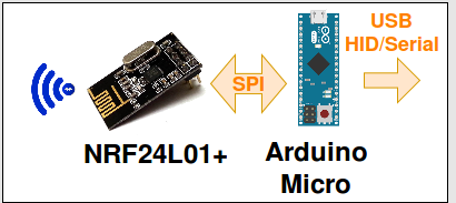
The Bluetooth receptor is wired to an Arduino Micro. Within this particularly impressive board there is an atmega32u4 (same as Arduino Leonardo) embedded which gives it the capacity to emulate HID devices and COM ports at the same time and on the same USB line. Through this, we are able to emulate a keyboard, a mouse, a joystick at the same time and still send data over the serial terminal.
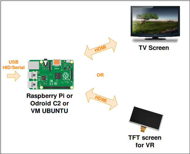
As it's probably the most commonly used computer by makers, I used a Raspberry Pi to analyse the incoming data and output the interface over HDMI. But you can also use any other computer OS as the code run on Python, as every computer emulates Python and reads HID and serial USB. I have only tested it on Linux for now.
The Python code provides 3 possibles outputs :
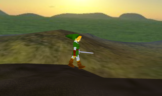
- Full screen, to play on a normal computer or TV screen
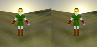
- Basic stereoscopic screen, to use with cardboard
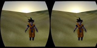
- Tunnel effect stereoscopic, to use on a VR headset with aspheric lenses.
It also provides several ways to interact :
- The Be Your Hero USB HID Sensors
- Keyboard & Mouse
You don't need to build the sensors & Arduino boards to test the code !!! The Python code has been tested on several linux machine including Raspberry Pi. You can use Mouse and Keyboard for control.
So this is our main hardware architecture... lets talk about software now!
Several years ago, a great contributor of the Raspberry Pi community built "Pi3D", a great light 3D Python library running on the small CPU/GPU of our favorite computer. He provided us with a full documentation and examples to start building games or platforms. To build the software I combined a Pi3D and VrZero to facilitate the Virtual Reality development. In addition I used Blender, a free professional software to build 3D objects.
By discovering the world of 3D Blender objects on the internet, I was amazed by the number of accessible drawings you can find. Basically, any of your favorite avatars, if they are slightly famous, have probably been designed a 100 times. So you just have to spend some time on the internet to find what you want ;). I found most of my designs on this website.
Step 2: Summary
There are several ways to publish a really big Instructable. You can write one very long tutorial with a lot of steps, or you can split it in several Instructables. This one is quite long, but I think it's still not detailed enough. So I will probably write other Instructables if I have recurrent questions on certain parts.
When I read an Instructable, most of the time, I am interested in the general concept of the project, or, in a very specific part of it. That's why I chose to split every main technical part of the project into 7 points. So you can quickly access the specific information that you need.

Step 3: Bluetooth -> USB/HID
Have you ever used HID devices?
Of course! You are probably using several right now!
HID stands for "Human Interaction Devices", it's the USB protocol used for Keyboards and Mouses and it's probably the easiest way to interact with a computer as it's recognized by any OS system.
Some Arduino boards like Leonardo or Micro aren't using the original ATmega328p AVR chip as UNO. They implement a Atmega32u4. The name doesn't seems very different... but this controller will give you the possibility to communicate with the USB port of a computer through HID. When you play with an Arduino UNO, you need to add a chip to interconnect the USB (like FTDI or 32u2) as HID is incompatible (except V-USB for AVR library, but the implementation is slower).
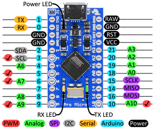
This HID capability will provide us with a great way to interface between Bluetooth and Raspberry Pi because we can re-use some of the Mouse or Keyboard libraries for an easy interaction and also use a Serial terminal communication for more complex data transfers.
Hardware
So, the hardware is pretty simple and can be re-used in many different projects:
- A Leonardo or Micro Arduino board. I used Micro to save space, but the Leonardo has a 3.3V power supply, which is useful for powering the Bluetooth. If you use a Micro, I recommend you to add an external 3.3V VCC.
- A NRF24L01+ on the SPI port (Pin 3/10/11/12/13, follow the schematic under).
- A button. To avoid headache, this safety button can block the HID. Sometimes a wrong loop can make your board send thousands of keyboard and mouse commands!!! Its only function is to say "send nothing if the button is pressed!"
- I used a tiny breadboard, some male/female headers and some wires to plug in everything together (See the picture above). I will try to optimize it and make a 3D printed box later when I will have finished other more important things :p
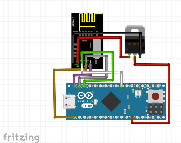
Software
All the software is available on this Github. For the Bluetooth HID, I had to manually add the libraries mouse/keyboard/Joystick (I use Arduino 1.6.9). This doesn't really make sense, as they are supposed to be already implemented...
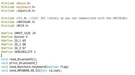
You can try removing the first three includes, then select Arduino Micro or Leonardo board and compile (Be careful, it's not going to work with UNO!). If it says keyboard, mouse or joystick not recognised, you have to download the library yourself "write arduino keyboard.h in google". Then you move them inside the Arduino installation folder (java/library in mac) and restart Arduino software!
The libraries you need depend on what you want. At first I was using a joystick lib, but it seemed to slow the Python code down. So I made another function to send data through Serial as well.
The mouse HID is very useful if you want to follow the movement of the head. So we keep the possibility of controlling our Python program with a normal mouse or with the Micro device.
Step 4: 6 DOF -> Bluetooth
DOF (Degree Of Freedom) Sensors
When I started this project, I hesitated a lot on what DOF sensors I should buy. It was obvious to me that I would need a 9 degrees of freedom to avoid the infinite rotating effect that 6 DOF would create.
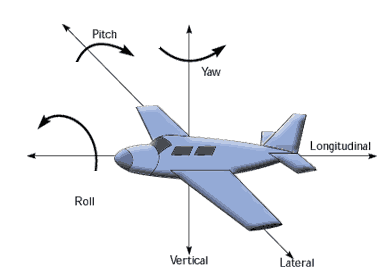
But then I discovered this code with a demo running on Free_IMU. It was perfectly still! Even after many random moves, the Yaw axe seems to be only a few degrees different while the Pitch and Roll stays perfectly level (see the plane picture above if you don't understand the three axes) which is perfectly fine for me for now... In addition, Eulers angles can be calculated with a "home reference position". Very useful for calibrating our sensors!
Hardware
The schematic of the device is above. Here are the components to build one :
- AirBoard, Arduino FIO or DIY solution. FIO Arduino bootloader runs with an 8MHz crystal (instead of 16MHz on the UNO) which allows it to be used in lower voltage. So if you have an Arduino project running on a battery, it is a great strategy to directly start with a 8MHz board (Or you can use the internal 8Mhz oscillator). Of course if your project needs the full performance of the UNO, this may create problems, but most of them don't...
- MPU 6050, 6DOF sensor which communicates with the Arduino over I2C
- NRF24L01+ Bluetooth chip which communicates with SPI. This board became very famous because of its great manufacturer NORDIC (which is a reference in BT devices) but also because of its amazingly cheap price : less than 1$! If we also consider the fact that it allows multi-channel communication, you have yourself a perfect toy to play with!
- Dip switch to select devices
- Lipo Battery
- Headers and wires to charge the battery and push the program.
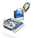
For debugging this project, I used several Arduino Airboard from a Kickstarter project. This amazing little board embeds a FIO, a Battery, a power switch, LEDs... Plus, it accepts remote programming over a dedicated BLE chip and a USB dongle. I recommend using those for debugging embedded battery projects, it will save you a lot of time!
Software
Processing test software (Also in Github here)
I already talked a bit about the library for the 6DOF sensor. If you want to give it a try, download this code and wire the sensor to an Arduino board. Once processing, start the IMU interface and you can start playing. The "h" key will recalibrate the sensor.
The Euler angles problems & solutions
Playing with 3D object rotations is a hard work. Using Arduino libraries and Pi3D helped me a lot to control the movement for one object. But I am still debugging a bit when the movement of one sensor depend on the movement of another. For example, hands movements depend on arms movements. So the angles of the hands have to be "HANDS_ANGLES - ARMS_ANGLES = REAL_HANDS_ANGLES". As Euler values aren't linear, "-ARMS_ANGLES" isn't the opposite of "ARMS_ANGLES"...
To implement this part, I worked on two solutions :
- SOLUTION 1 : The nodes send only the 4 quaternions on Bluetooth. The central receive and calculate Euler angles. When the quaternions of the hands is received, the Euler is calculated depending on the arms quaternions as "home reference". This solution works, but the central needs more time to calculate.
- SOLUTION 2 : My first choice was to calculate Euler angles inside the nodes and send them over Bluetooth (which is nice because I still have one empty byte on the buffer for the button). In Pi3D I tried to implement the Hands depending on the arm, but it's still not working perfectly right now. If you are interested in this topic, you can take a look on the conversation I had with paddyg here.
Calibration
As you can see, those 6-DOF sensors are quite precise. But without a compass, they need a YAW calibration. On Free_IMU, the key 'h' set a "home calibration". In my solution, one of the Nunchuck button trigger the "home calibration" in the central. So if your sensors seems to have a wrong orientation, just press the button and take the same position as your avatar when all the angles are "0,0,0". To simplify, I always draw my avatars in the same initial position.
Bluetooth library
There are a lot of NRF24 libraries online. Some didn't work with my application, and more specifically because of the 6DOF library delay which probably caused synchronization problems... So use this one, it seems to work very well with other libraries ;)
DIP switch
Using multi-transceiver Bluetooth, you are going to need different addresses on each node. That's why the DIP switch is here. You can load the same program in every 6DOF node and only play with the switches to give them different addresses. You forgot to charge one of your nodes? No problem, take another one, set the same DIP address, and that's it!
Packaging
Sorry, not finished this part yet, I will send some STL 3d print files as soon as I can
Purpose of the device :
- Records the body's movement through the 6DOF sensors over I2C
- Analyses the data and creates the 4 Quaternions to determine the position
- Calculates the three Euler angles. In case a reference point has been defined, the Euler angles will also depend on it
- Casts each Euler angle floats into a byte, so we can send all three in one message (4 bytes buffer limit). This action reduces the number of possible values to 256 per angle... but it speeds up the communication a lot.
- Sends the Buffer
- Enters shortly into Reception Mode, so if a new referencing point has been set, it will be taken into consideration. (This part is changing on the last version)
Step 5: Nunchuck Joystick -> Bluetooth - General
General
Controlling the body movement is nice, but when you have a Virtual Reality headset in front of your eyes, it's not a good idea to start walking around... That's why I use a Wii Nunchuck joystick, so your hero can move around freely without running the risk of you kissing a wall!
Hardware
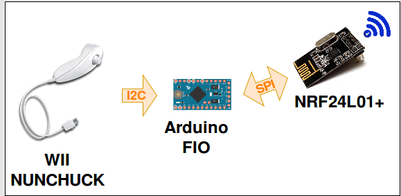
The construction of this device is almost identical to the 6DOF peripheral from Part 2. Except that instead of using a 6DOF, we connect the Nunchuck onto the I2C. We can also remove the DIP switch. As you may notice, the Wii Nunchuck plug is not exactly an Electronic standard, so it would be pretty hard to find a female one on Sparkfun... Luckily, in part 6 of this tutorial, I'll explain how to hack a Wii camera. If you plan on doing this part, you can take the female plug from the dismantled remote. If you are not, you can cut the cable and solder directly the wires through a standard connector (like a male header for example)
Software
Sources here. To easily implement the detection of the joystick and the buttons, I recommend using this library XXX. It is very fast and easy to understand, so the peripheral Nunchuck Joystick code is really simple once you have understood how the NRF24L01+ works.
Packaging
Also working on it!!
Step 6: Wii Remote Camera -> Bluetooth - General
This part isn't fully finished yet. It's more of an add-on, if you want to go further by tracking your movements inside a room.
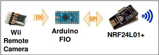
Wii remote camera is an amazing little sensor. With just a 25MHz quartz and a few resistors it gives you the possibility to track a maximum of 4 IR LEDs. We could, of course, use any Camera to do this, but the particularity of this one is to directly send you the X,Y coordinates. So you don't need any processors and openCV, a simple micro-controleur can perfectly read the data and trigger different actions. This is a really amazing feature for this device to be able to run with a simple Arduino Uno.
The only problem is to find this sensor. I couldn't find any online stores to buy some, so I had to extract it from a full Wii remote. As you can see on the pictures above, when you don't have the good screwdriver it can become a bit messy...
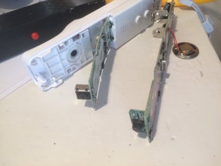
Finding this little Camera was even harder than I thought, as some Chinese brands made some copies of the Wii remote. So you need to find an official Nintendo one. Here is a link to help recognise real ones from the fake ones (in French sorry but the pictures are useful). I think some people have successfully hacked the Chinese copy as well, if anyone finds a bit of code, it would be very useful! If not, I will try to hack it myself in the next few months to write a library.
I will soon post the hardware and software to link those sensors to the NRF24L01+.
Step 7: Load a 3D Python Map on Raspberry Pi or Any Other Platform
All right, after all this hardware and embedded software, let's take a break and talk a bit about Raspberry Pi, Python and Pi3D.
As you probably know, Python is already installed on RPi Debian. There is a big community using it, and it is easy to find some help. To start playing with 3D, I discovered, a while ago, the library Pi3D (homepage here) which works very well. Everything is well documented from installation to documentation and of course running some demos. All the information you need is in here. I don't really like to re-write existing tutorials when they are so well documented. I will write a "quick setup start" if some people struggle with it later.
When the installation is done, you can go to pi3d_demos and start playing with all the .py you can find. I actually spent a very long time running all those examples, because they give you a lot of information on what Pi3D can do! The image above is from Forest_Map which is one of the examples I used to create one of the BeYourHero maps!
For example you have :
- BuckfastAbbey.py running a map with a .egg light model and textures of an Abbey
- ClashWalk.py showing the forestWalk with blocking real-life objects
- Earth.py shows you how to configure the Camera to turn around a reference point.
And so on...
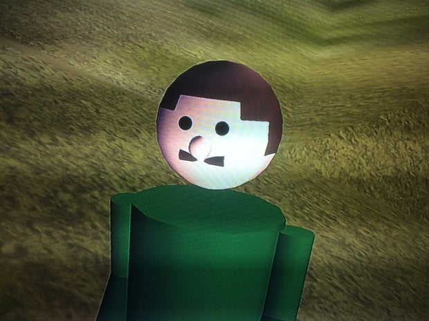
At this point, I didn't realize how powerful it was to import Blender objects. So I started designing my own Hero using only spheres and cylinders. You can see my friend "Roger" here. He is able to move his head, arms and legs when he runs, or looks around.
Step 8: P5 - Make Your Hero Ready for Blender Custom!
So now we have our 3D environment running, let's start finding our favorite Hero!!
Blender is a Free professional software to create and manipulate 3d objects. I would say it is really complex to be able to use the full capacity of the tools provided. So if you want to draw your Hero from scratch, I am afraid that's way too complicated for me to help you...
But luckily, Blender has a really big community, which means... A really big open source database!
So we can find thousands of objects by just looking on the internet. This website particularly helped me with finding many console avatars. If the object is a ".blend", we can open it directly with Blender. If you have a ".obj" file, you can create a new file and import it.
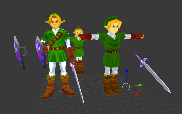
If you are running Pi3d on a Raspberry Pi, you should be careful with the complexity of the object. The more vertices and complex textures it has, the more it will slow the program down... And if you want to use the VR on a Raspberry Pi 3, we are going to have to forget all the complex forms :-( That's why I chose Link from Nintendo 64 and not the one for Wii (on the picture above).
More advice on how to use Blender basic functions, will be given in the following steps :p
Step 9: Load Your Object Into Pi3d
- The generated .obj file contains the shape, it is really necessary!
- The generated .mtl file contains the links to the textures (the colours). If the textures of your Hero come from an external ".jpg" or ".png" file, the ".mtl" it will contain the paths to find those textures and fit them onto the correct surfaces. So I strongly recommend you to store all the files in the same folder, you can do this by using the "copy" option when you export an object.
So now we can load our object into Pi3d with the command :
self.body = pi3d.Model(file_string="PathOfYourFile")
If you stored the .obj, the textures and the .mtl (with a good link) on the same folder. Pi3d should recognise the textures and your hero should have colours. As every 3D files seems to have different sizes, your Hero is probably going to be very big or very small. Adjust this with
self.body.scale(X, X, X)
Congratulations, now your hero should be on the map! But... He is not moving at all!!
Step 10: Transform Your 3D Hero Object Into Multiple Objects With Blender
As you've imported your Hero as one object, you can't move your Hero's parts individually. At this point we are going to have to go back on Blender...
Basically, the idea is to split your hero into several parts. If you import those separate parts into Pi3D as different objects, you will be able to create rotations and translations between objects. But to do this, we are going to have to understand a bit more how to use basic Blender functions :
- Blender projects are ".blend", if you have an ".obj", you can create a new project and use "import .obj"
- Use the "copy" function when you export your ".obj" so the texture goes with the model (paths inside ".mtl")
Import your full model. If no textures are applied select "object mode" at the bottom and then do "Alt a". The textures should appear. Let's "center" or hero, I'll give you only the very useful keys :
- Adjust the central point of view by clicking on the shift and the central mouse button
- key A is for selecting/unselecting everything. --> select all your hero
- Rotate your hero on the main three axes to simplify : keys "r x" "r y" "r z". To simplify the import, always stay at the same reference (I used Green arrow on the back, red on the right and blue on the top, look at the pictures with Link's head above).
- Click on those three arrows to rotate and centralise your hero in the middle of the grid (I chose to have the center of the feet as a reference point, I am not sure if it's the best, but it worked well for me...)
- Press "n" and set 3d cursor location to 0, 0, 0.
- If you are still in object mode, you can go to object/transform/origin to 3d cursor. This will set the origin to the 3d cursor you referenced at 0,0,0.
- Save your file as blender "Full_body_hero"
Now let's start splitting the hero :
- "Save as" your project as "head_hero" to keep the original one.
- Select "Edit mode" and "wire frame" at the bottom. You can also use Solid to visualise if you are not making any mistakes.
- By clicking "C" you access the selection cursor. Select every point you want to remove and press X to delete them (be careful and do it in several goes, you should not remove any points from the head here).
- When all the parts are removed, click on vertex select (on the right of where you choose the mode).
- If you entirely remove the neck from the head as I did, you will have some kind of a hole inside. Right click on all the surrounding vertex of this hole (keep shift key so select several). Then press "f" to create a face. If the created face is white, it often means that you have wrongly selected the vertex...
All right, now you have the first part of your hero. You are going to have to do the same for all the parts you want to rotate. It's a bit long, when when you start getting use to blender, it goes really fast! Do not move the parts you are creating so the reference cursor stays at 0.0.0. When you will import your parts to Pi3D, your hero will be perfectly assembled!
To encode Link, I used parts you can see on the picture above :
Head, top body, arm left, arm right, forarm left, forarm right, hand left (I added the blade to it), hand right (I added the shield to it), body, leg bottom left, leg bottom right, foot left (with bottom of leg left), foot right (with bottom of leg right)
Once you have imported all the parts, you can go to the next section to learn how to rotate them individually.
Step 11: Load Your Hero in Avatar.py File
Let's load the hero onto python Pi3d now!
As you can see on the Github, I have created a Class avater for every character I wanted to load. I chose to start with the body object, as for me, every body part is attached to it...
This Class is quite simple, to load an object use :
self.body = pi3d.Model(file_string="PATH TO THE BODY PART .obj", name="Link");
Then add a shader to make the texture look better. Try a different one and see which one is the best for your Hero (uv_flat, uv_light, uv_bump...).
shader = pi3d.Shader("uv_flat")
Set the scale to dimension your object (do it only once for the body).
Do the same to create the head and attach the head to the body by doing :
self.body.add_child(self.head)
Go to run.py and replace Hero = human.link() by Hero = human.NAMEOFYOURCLASS()
Press enter and your hero should appear.
When all the parts are integrated, try to rotate the part individually. It should work but with the wrong rotation references. You are going to have to adapt this for every object by using cx, cy cz when you load each part (See the examples with Link or Goku). Make an infinite rotation a part and modify values of rotation to find the exact rotation location.
Now your hero should be ready to be loaded. So run your program again, and see if he appears on the map.
Step 12: Start Gaming!
When your hero is ready for his first quest, Be Your Hero ! will allow you to play your first game. I am going to need few more days to finish the scenario.
Step 13: And the World Become Stereoscopic...
Once your Hero is fully imported, it's now time to understand the Python code a bit more.
The code is split into several files :
- run.py is the game
- serial_data.py is taking care of the Threading and the serial communication
- avatar.py contains all the links to the Hero's parts.
- map.py contains all the maps available
You don't have to understand everything to make it work or even modify things. But take a look at the beginning of game.py to find the config :
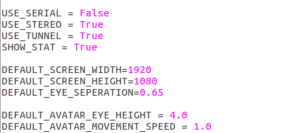
Here you set True or False depending on the configuration you want. You can plug the serial USB/HID
Bluetooth, set the "USE_SERIAL" to "True" and restart your program.
Turn the joystick and your nodes on, your hero is now following you! (everywhere)
It's the same to activate all effects : set "USE_STEREO" to True and your screen will be split in two. "USE_TUNNEL" will activate the tunnel effect...
Step 14: Build Your Own Multi-platform Virtual Reality HDMI/USB Headset
To test your program with stereoscopic effect, I used a very simple and economic solution : a ColorCross headset and a 5" TFT HDMI screen!
Using this, you can directly attach your screen onto the headset as if it were a smartphone. Plus, the TFT runs at 5V so if you want to be fully independent from wires, you can plug a 5V battery and power the Raspberry Pi and the screen together. With this solution you are fully free to move (but be careful of walls!)
Another great solution would be to adapt the python software to run on Android. In this case, we could use an OTG USB cable and run our sensors directly onto an Android smartphone. Or an easier solution would be to use an existing Android game and adapt the sensors to it, if you have any ideas I would really like to help create new applications for this project ;)
Step 15: P9 - Build Your Own "High Quality" Headset Using Laser Engraving Plastic Parts and Aspheric Lenses
For this part, I got a lot of my inspiration from The Nova project. It gives you all the details that you need to understand the use of aspheric lenses.
But I am actually working on another design to adapt the lenses. I have to go back to the Fablab to run some tests on a laser cutting machine. I'll post the design soon !
Step 16: Still Many Things to Improve!
As you probably saw with the many steps of this tutorial, there is still a lot to do!
Here are the parts I am working on right now :
- Design for the HD headset
- 3D print box for the sensors
- Multiplayer and online game. This part is to allow several users on the same map. It's still being developed.
- Trying some new scenarios using Wii Remote cameras
- Design and implement a nicer game scenario with different levels
- I am also working on adding a Sonar to detect real object and to add inside the virtual world
Step 17: And Also So Many Things to Imagine!
All right, here is an interesting part : What can we imagine to improve this project?
Here are few ideas, but the list is probably going to get really big :p
- Multiplayer online gaming
- Android application to interface sensors with smartphone
- Using BLE with the sensors to improve batteries
- Create a big library of avatars to be able to load many different heroes and enemies
- Improve gaming possibilities with an immersive Super Smash Bros??
- Create more "movement sequences" to be able to play with normal gaming remotes or keyboards
I am waiting for your ideasin the comments!! I'll add them to this step.
Step 18: Conclusion
OK... what to say...
This project has been really amazing to work on, it gives you some tools to imagine thousands of scenarios and ways to interact. I will keep posting improvements regularly, so come back soon if you want to see more!
I really hope you enjoyed reading it, and if it will help you design something. Keep me posted! I want to see what you come up with:)
Step 19: I Would Like to Thank
First, I really want to thank paddyg who helped me on the Raspberry Pi Forum a lot. As one of the designer of the library Pi3D, he is really good in Python!
I also had a lot of advice from Stephan who made the great VR design using two TFT screens.
Thanks to Wayne Keenan for his Vr-Zero library. I don't think I would have been able to implement the stereoscopic effect without this lib.

Participated in the
Arduino Contest 2016

Participated in the
Epilog Contest 8

Participated in the
IoT Builders Contest


