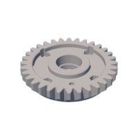
Introduction: Robotic Gear Arm Could Be Used for 3d Printing
The goal I wanted to give the robot
It is to make a model and demonstrate the force of its force transfer system through gears and with this also generate touch.
Ball bearings are used to reduce friction and make the robot move more harmoniously. The robot is designed to have a low center of mass.
A tx source was tapped to provide a 12v and 5v power supply for the motors and plate respectively
Step 1: hardware
The control system uses an Arduino Mega with a RAMPS 1.4 board and A4988 drivers. I provide a solid and functional programming foundation for the Arduino, which handles the interpolation of the stepper motors, performing all the geometric calculations, and smooth accelerations. It can handle some kind of serial GCODE communication.
Step 2: Turntable
Turntable
It has a bearing so that the stepper motor can be actuated and the flexibility of the arm can be controlled as a step.
The fully extended robot arm at the top multiplies every gear and bearing tolerance it has.
Step 3:
It is this part of genera and carries mechanical energy
It is composed of the impreza parts (h, locks), bolts, stepper motors and gears.
Step 4: Acoplamiento De Motores
It is this part of genera and carries mechanical energy
It is composed of the impreza parts (h, locks), bolts, stepper motors and gears.
Step 5: Base With Roller Bearing Gives Degrees of Freedom of Rotation
Step 6: Mechanical System Name
for arm (coupling of bearings preferably to place them using a press, I use a small press against a table they are not very expensive in hardware stores these 3 or 5 dollars)
Step 7: Motor and Electronics
Nema 17 motors of 0.6 were used, which gives you the precision unlike servos, an Arduino mega and a 1.4 ramp with its 4988 driver to control the motors and a tx source you can take out of an old computer and bridge the cable green with a black one so that the source turns on every time you feed it with AC
Step 8: Body
Step 9: Piezas Stl
here is all the stl so you can print it on your 3d printer
Attachments
 base.stl
 base_w_hole.stl
 baseRing.stl
 control_bottom.stl
 control_top.stl
 doc3.pdf
 GearBig_0.01mmTolerance.stl
 GearBig_0.05mmTolerance.stl
 GearBig_0.10mmTolerance.stl
 GearBig_0.15mmTolerance.stl
 GearBig_0.20mmTolerance.stl
 GearRotate_0.01mmTolerance.stl
 GearRotate_0.05mmTolerance.stl
 GearRotate_-0.05mmTolerance.stl
 GearRotate_0.10mmTolerance.stl
 GearRotate_-0.10mmTolerance.stl
 GearRotate_0.15mmTolerance.stl
 GearRotate_-0.15mmTolerance.stl
 GearRotate_0.20mmTolerance.stl
 GearRotate_-0.20mmTolerance.stl
 GearSmall.stl
 gripperBase.stl
 gripperFinger.stl
 gripperHolePlate.stl
 leg_30mm.stl
 leg_35mm.stl
 leg_40mm.stl
 leg_45mm.stl
 leg_50mm.stl
 lever.stl
 lowerShank.stl
 manipulator.stl
 pleuel.stl
 pleuel_bend.stl
 robotGeometry.pdf
 socket.stl
 socket_clearanceWoSetScrew.stl
 stabilizer.stl
 stabilizer_endstop.stl
 step.zip
 triplate.stl
 upperShank.stl
Step 10: Codigo
code
Step 11:
Step 12:
Step 13:

Participated in the
Metal Contest


