Introduction: Breadboard to Custom Arduino Shield


In this instructable we will make a custom Arduino shield using 123D Circuits.io for our previous instructable project: Running leds
Step 1: Editing and Placing the Components
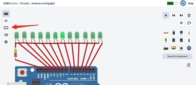
First open the PCB view. Now you can select a component and change its footprint. The default for LEDs are SMD but I'll change them to 5mm through-hole LEDs because these are far easier to solder.
Now place the components on the Arduino shield (inside the purple rectangle). I resized the shield by dragging the purple outline so I could place all the LEDs in a row.
Now place the components on the Arduino shield (inside the purple rectangle). I resized the shield by dragging the purple outline so I could place all the LEDs in a row.
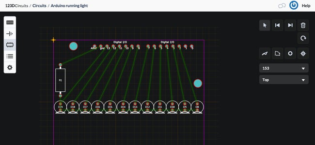
Step 2: Routing the PCB
A printed circuit board consists of copper traces on a glass-reinforced epoxy carrier. We now need to draw each of the electrical connections that will make up the PCB.
The green lines, called "airwires", denote the electrical connections that you need to route as copper traces. These come from the breadboard design you made earlier. This process of is called "layout".
Switch to the routing tool and click a pad to get started. Route the trace by moving your mouse and clicking at intermediate points until you reach the other side of the airwire. Make sure not to cross or come too close to other lines. The tool will show a warning when you make a mistake.
Repeat this process until all green airwires have been routed. You can also draw connections on the other side of the PCB if this make routing easier. You can switch and route traces on the other side of the printed circuit board by selecting the correct layer in the selector. It is even possible to switch layers while in the middle of routing a trace. In doing so a small hole called a "via" gets added to the trace, this hole will be plated with copper and conduct electricity to the other side of the board. If your board has 4 or 6 layers instead of 2 layers the drill holes for the vias will go all the way through the board but only electrically connect the two layers associated with that part of the trace.
Step 3: Done?


When all the traces are routed go back to the project overview and click "Mark as done". Now the design will show up in the gallery and other people can see it. It is now also possible to order the board.
Step 4: Order Your Shields

I you want to order your shields click on "Buy 3 boards for..." Fill in your order details and you will receive high quality PCBs in about two weeks. With free shipping world wide!


