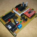
Introduction: Build Your Own Arduino
Setting up an Arduino on a breadboard has become a process I have grown to love.
Within a few minutes you can have a fully working Arduino platform to work with as you will see in this tutorial. There have been several occasions when I was at school and quickly put together one of these for testing some ideas for a project. Plus it is just looks so neat with all the components laid out over the breadboard.
Some of my Arduino Projects
Whats is an Arduino?
Arduino is an open-source electronics prototyping platform based on flexible, easy-to-use hardware and software. It's intended for artists, designers, hobbyists, and anyone interested in creating interactive objects or environments.
Arduino can sense the environment by receiving input from a variety of sensors and can affect its surroundings by controlling lights, motors, and other actuators. The microcontroller on the board is programmed using the Arduino programming language (based on Wiring) and the Arduino development environment (based on Processing). Arduino projects can be stand-alone or they can communicate with software on running on a computer (e.g. Flash, Processing, MaxMSP).[1] www.arduino.cc�
Step 1: Components
* See note about the TTL-232R cable in programming options before purchasing.
You can buy components at www.ArduinoFun.com or www.SparkFun.com or www.CuriousInventor.com or www.FunGizmos.com or www.Adafruit.com just to name a few places off hand.
Origninal tutorial by: http://itp.nyu.edu/physcomp/Tutorials/ArduinoBreadboard
Step 2: Setting Up Power
Step 3: Arduino Pin Mapping
Step 4: Component Hook Up
Figure 1-7: Supporting circuitry pins 1-14
Referring to Figure 1-7, locate a spot where you have 6 columns on the breadboard that are not in contact with anything else. Place a row of six male header pins here.
Step 5: Programming Options
- FT232RL USB to Serial Breakout Board, SKU: BOB-00718 (This option takes up more space on your breadboard)
- FTDI Basic Breakout - 3.3V SKU: DEV-08772 (This option, and using right angle male headers works the best out of all three because it is secured better on the breadboard)
- Arduino Duemilanove w/ATmega328
- Arduino Decimila, Duemilanove or Nano w/ATmega128
- No Power – Make sure your source power is above 5V.
- Power but nothing works – recheck all your connection points.
- Uploading error – Refer to www.arduino.cc and do a search on the particular error message you receive. Also check the forums as there is a lot of great help there.
Step 6: PCB Files
If anyone is interested in etching their own PCB (printed circuit board) I have included the component and solder side pcb files.
I have added a zip file which contains 300dpi JPG files of the component side and solder side.
If you have questions, feel free to email me and I will help you out the best I can. Just note I have classes throughout the day, so sometimes my replies can take a day to respond.
2 People Made This Project!
- WayneHuang made it!
- c_rider made it!
134 Comments
2 years ago on Introduction
Sorry but there is nothing such as a "Arduino Programming Language". Arduino is programmed in C++.
Reply 5 weeks ago
A nuance here, Auduino's are programmed with the Wiring language, a programming language built on C++. https://en.wikipedia.org/wiki/Wiring_(development_platform)
2 years ago
Project videos unavailable.
3 years ago
can any one help me with this error message pls
avrdude: ser_open(): can't open device "\\.\COM3": The system cannot find the file specified.
4 years ago
Can I add any other FTDI breakout board?
5 years ago
pls
5 years ago
Who has a spare arduino board please give me:)
5 years ago on Step 4
amazeing thank you
5 years ago on Introduction
To be absolutely correct and avoid any risk of oscillations on the 5V line due to sudden load changes, especially considering the distances of the wiring around the 7805, there should be two additional ceramic capacitors of 100nF each from the input and the output of the 7805 to the ground. These are normally 2.54mm spaced lead components that are fitted into the board next to the regulator. There is space available on the breadboard to be able to fit these easily.
5 years ago on Introduction
Do you really need a 440 tie point breadboard rather than a 400 one? I can't seem to find a 440 pin
6 years ago on Introduction
I will definitely try this out! :D
6 years ago on Introduction
That was very easy to make!
Thanks for the elaboration! :D :D
7 years ago on Step 5
In the Arduino IDE, Go to file>preferences and turn on verbose output on UPLOAD.
Close the preferences window.
Now click Upload.
Your sketch will compile and when you see the baud rate or "send" in the output, press reset.
Hope is works.
Should work for avrdude in the cmd/terminal.
Also! With this method you only need the 5v, Tx, Rx and GND from an FTDI or UART/TTL programmer. No DTS or RTS,
Some UART boards have a line marked RTS or RST. Don't use these.
Reply 7 years ago on Step 5
This is if you get the "out of sync" or errors on upload.
7 years ago on Introduction
Hi! Great tutorial. Can a normal USB cable be used instead of the 232r converter here? I have plenty lying around that I could just rip open.
Søren
7 years ago on Introduction
hi sir, good day, cn u give me an schematic of this? so that i cn make my own modified arduino, pls T_T i need it badly coz we are ask by our prof to make our own modified arduino, T_T pls...i need reply asap sirT_T
7 years ago on Introduction
Very nice man! An old post of yours rang in at $15. Does your price include a breadboard, or just components? I'm looking at cost cutting for arduinos.
10 years ago on Step 5
hey...no one has asked about the bootloading thing....
Its Important....
Reply 8 years ago on Step 5
This 'ible is only about Arduinos, Arduino is basically an ATMEL chip with the arduino bootloader installed. You can purchase certain chips that come preloaded with the bootloader from places like sparkfun or you can upload your own to blank chips (save a little $) but you will need to lookup ISP programmers, which ironically can be created with an arduino.
8 years ago on Introduction
awesome 'ible ! got this one bookmarked for my up and coming arduino adventure!!!
one quick question though... how did you create the simple breadboard diagrams ?
i want to be able to create these too so i can preserve my breadboard designs without having to take photos from multiple angles to document my work ???
please help if you can, i know this is an old ish 'ible & may not get a reply but i would be very grateful if you could point me in the right direction!
many thanks in advance ;-)