Introduction: Build a Giant 3D Printed Robot Arm
Have you ever wanted to build a giant, 6-axis, mostly-3D-printed robot arm? Well, this Instructable will show you how to do exactly that. Using a large collection of 3D printed parts, stepper motors, a 3D printer control board, a power supply, and a big pile of off-the-shelf hardware, we will create a large and powerful robot arm.
Robot Degrees of Freedom
Shoulder
Elbow
Wrist Twist
Wrist Tilt
Gripper
Base Rotation
Credits
- All of the design work for this project was done in Autodesk Fusion 360.
- The assembly animations featured in most of the steps in this Instructable were created using the Animation Workspace in Autodesk Fusion 360.
- The robot arm in this Instructable was heavily based on the Moveo robot by BCN3D Technologies. In this Instructable I modified the way all the parts attach together to make assembly easier. I also use a different control platform for the robot. Finally, the base on which the robot sits is different in this Instructable than in the BCN3D Moveo.
Step 1: Gather Your Parts
A fairly large collection of parts are required for this build. Below is the bill of materials for this project. The document has two tabs, the first lists all the parts required to build the 3D printed robot arm, along with sources for parts and approximate prices. Depending on when you order your parts, the prices and availability might be slightly different, but the bill of materials should be mostly accurate. You can access the bill of materials by clicking the Google Sheets link below.
The first tab of the document is the actual bill of materials. This tab lists every part, other than the 3D printed parts, needed to complete this project. I also provided a link to where you can purchase the parts. There are probably any number of sources for the parts, so feel free to shop around.
The second tab of the document lists the materials required for each sub-assembly of the robot arm. This tab is a useful reference as you progress through this build in case you face any confusion about which parts are needed for any particular step.
The total cost for all the parts involved in building the giant 3D printed robot arm is roughly $600. However, the majority of the parts, especially all of the hardware, is typically available only in packages of much larger quantities than is required for this build. Therefore, the cost is likely to be quite a bit higher than the actual cost of the materials used.
Step 2: 3D Printed Parts
The entire structure of the robot arm in this Instructable is made from 3D printed parts. There are quite a few parts involved. Some of the parts are quite large and will take some time to print.
If you don't have access to a 3D printer, or if your 3D printed lacks the build volume for some of the larger pieces, 3D Hubs is a fantastic resource for getting 3D printed parts made quickly and affordably.
All of the STL files you will need to print the parts are available in the GitHub repository for this project.

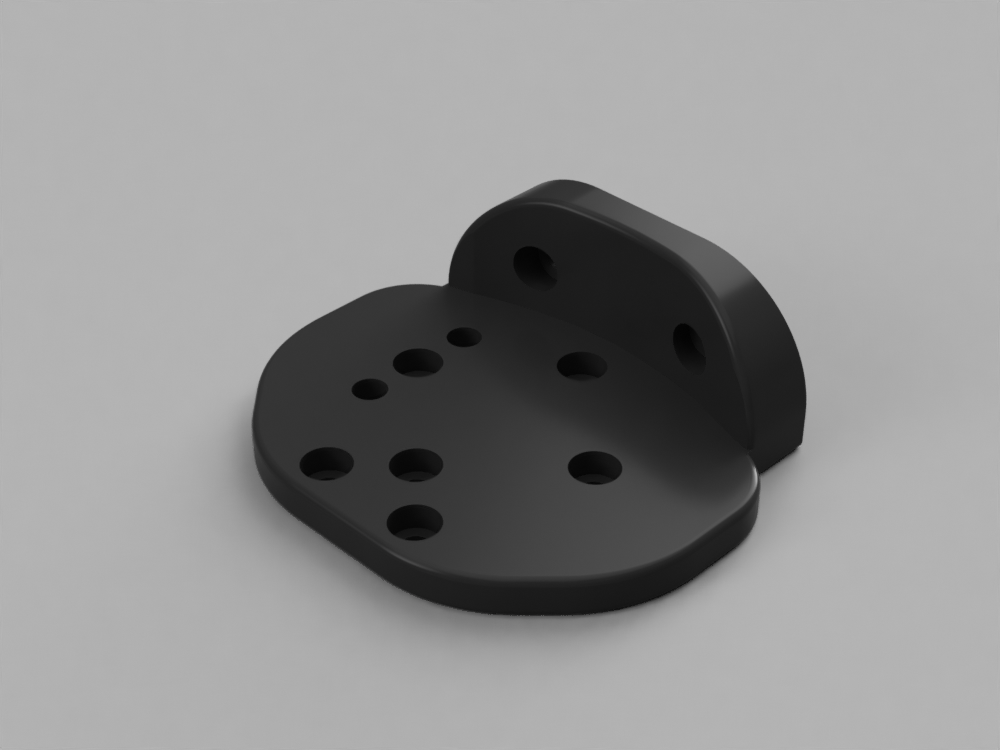 Gripper Top Plate Quantity: 1 | 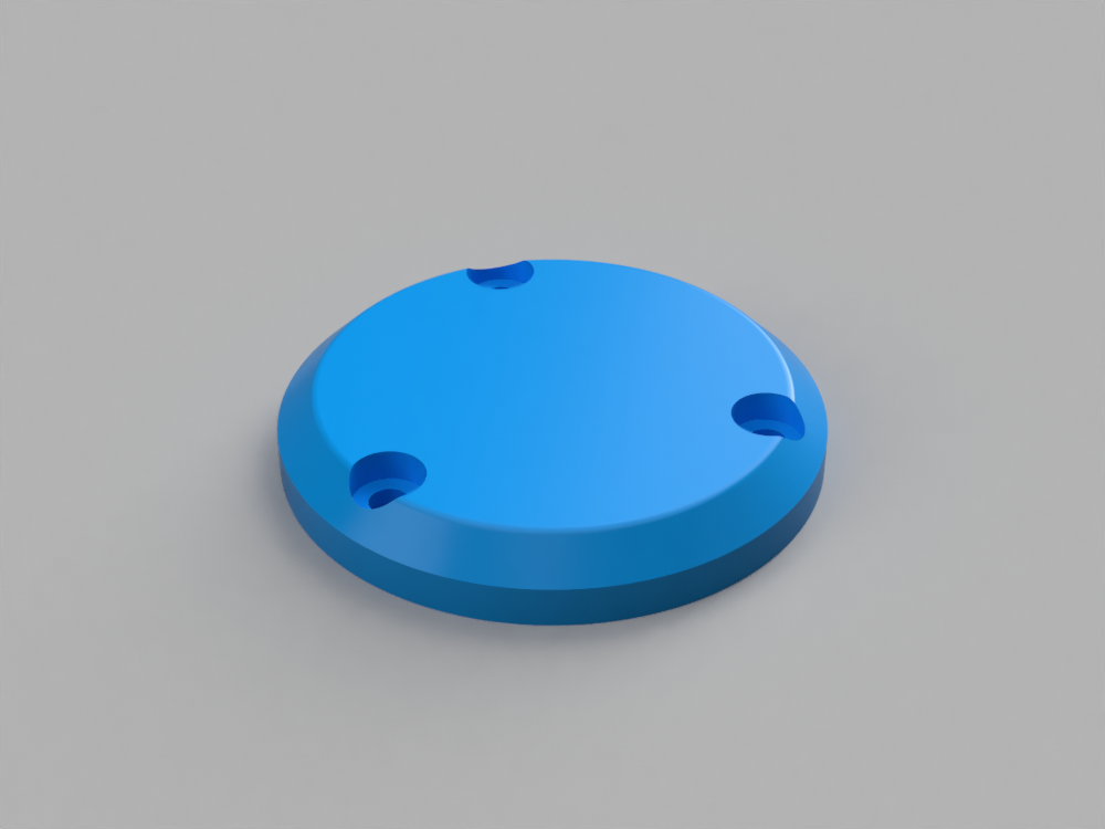 Elbow Shaft Cover Quantity: 2 | 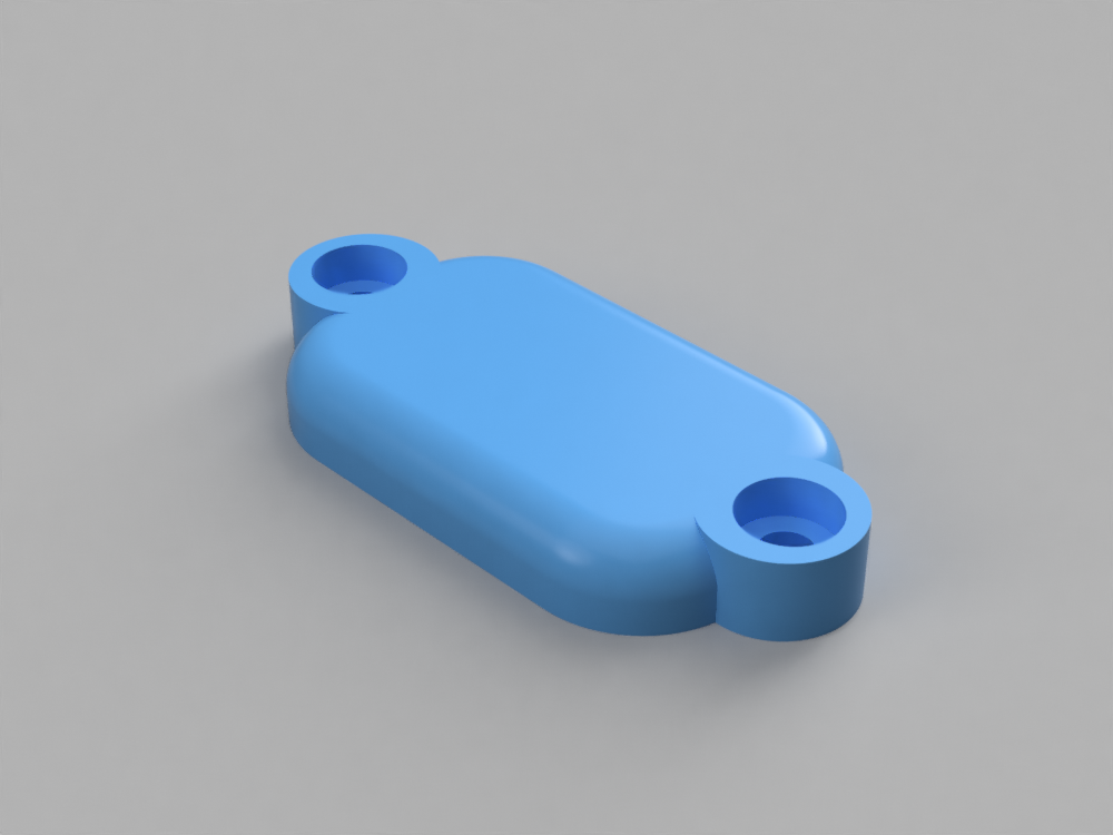 Wrist Back Cover Quantity: 1 |
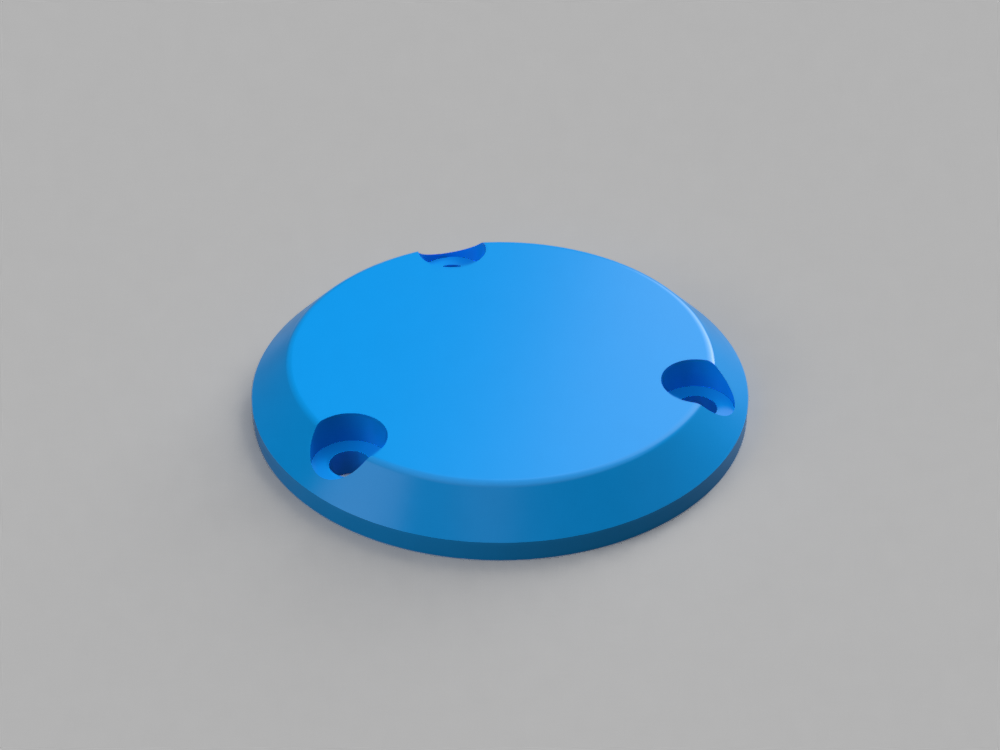 Wrist Shaft Cover Quantity: 2 | 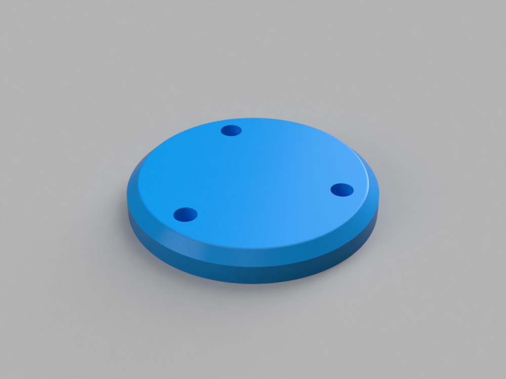 Shoulder Shaft Cover Quantity: 2 | 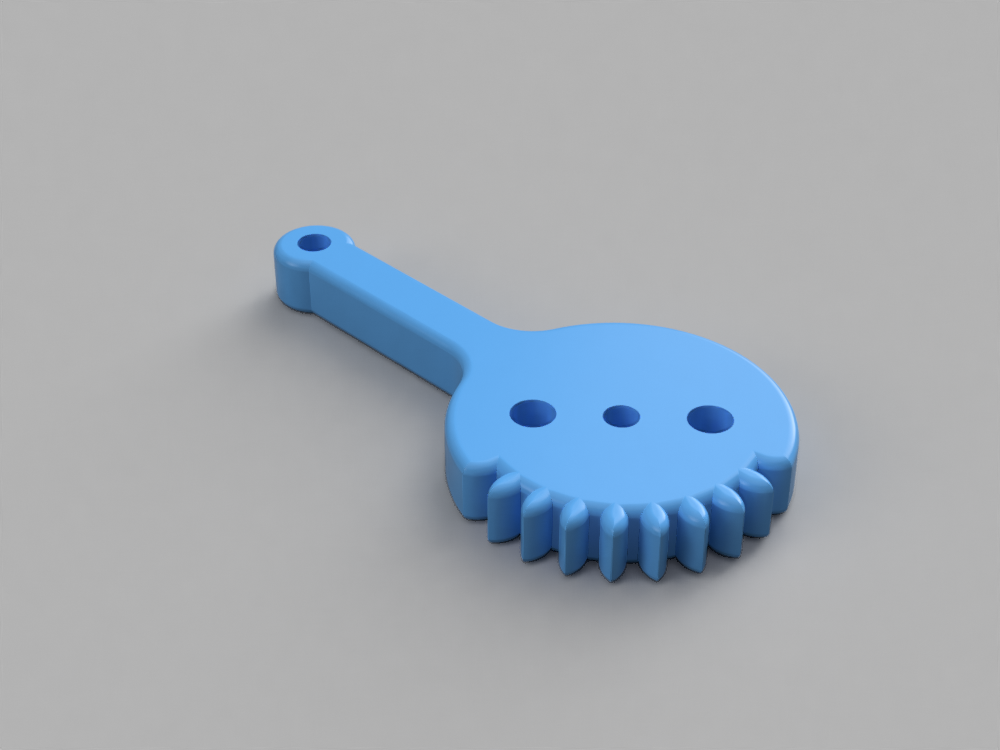 Servo Gear B Quantity: 1 |
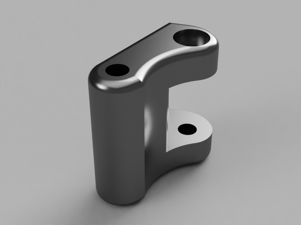 Elbow Belt Tensioner Quantity: 1 | 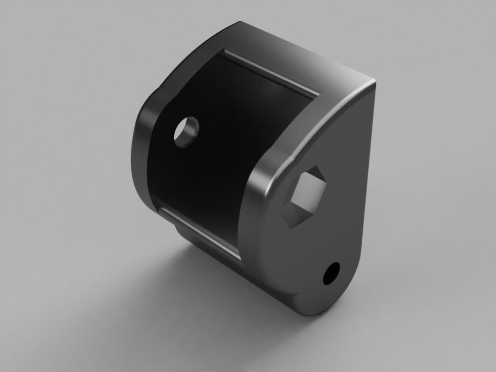 Wrist Belt Tensioner Quantity: 1 | 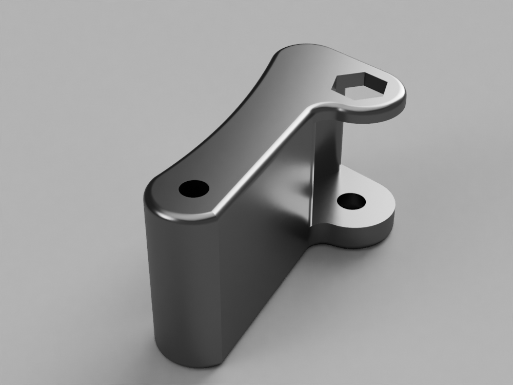 Shoulder Belt Tensioner Left Quantity: 1 |
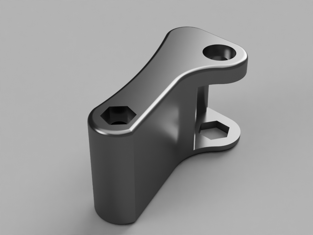 Shoulder Belt Tensioner Right Quantity: 1 | 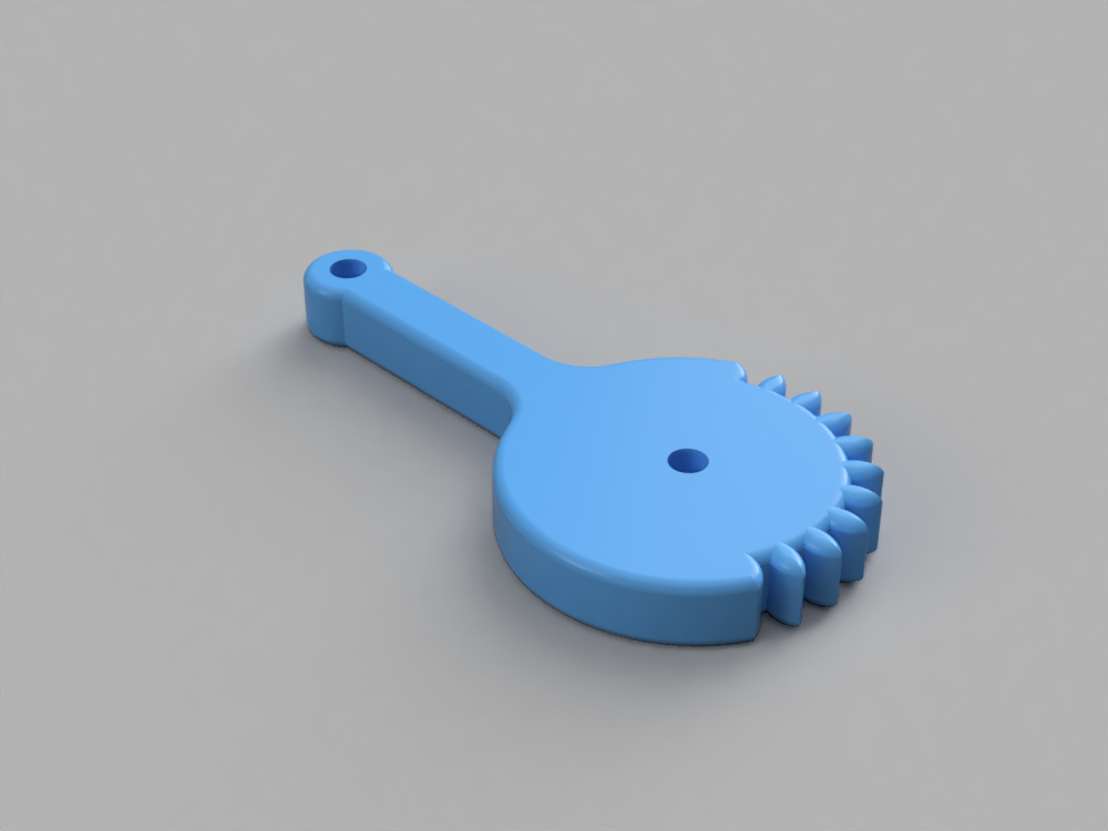 Servo Gear A Quantity: 1 | 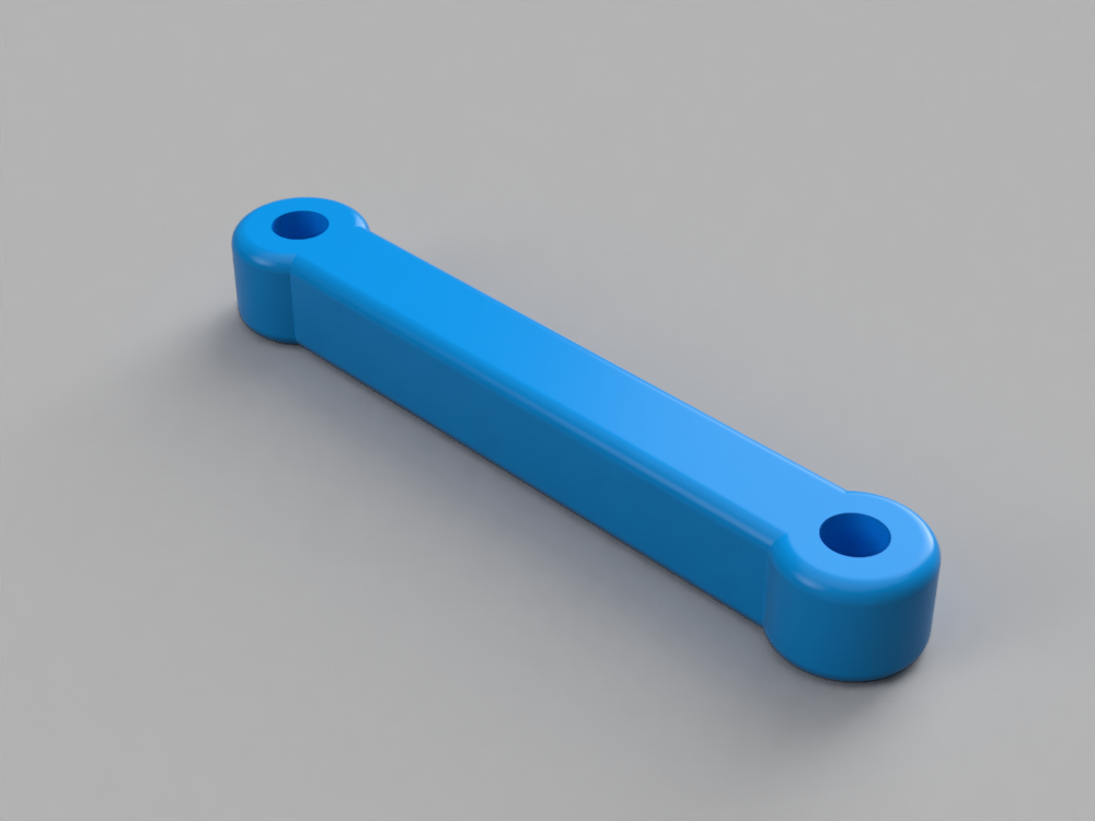 Pivot Arm B Quantity: 2 |
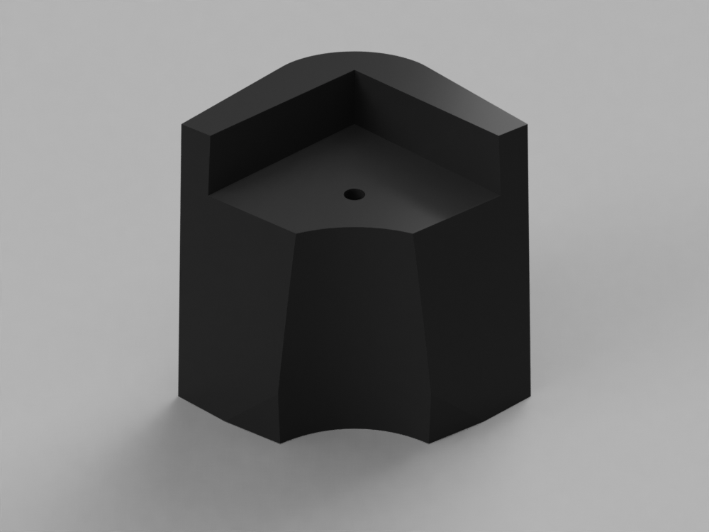 Base Legs Quantity: 4 | 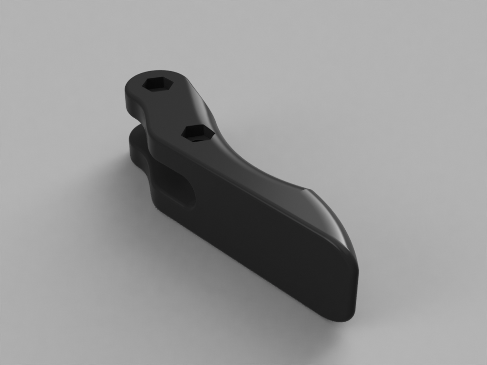 Gripper Right Quantity: 1 | 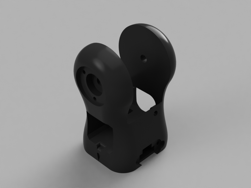 Wrist Base Quantity: 1 |
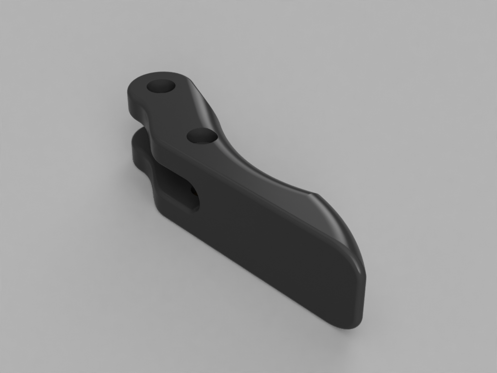 Gripper Left Quantity: 1 | 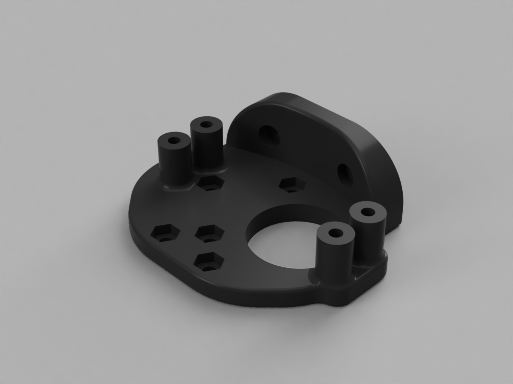 Gripper Bottom Plate Quantity: 1 | 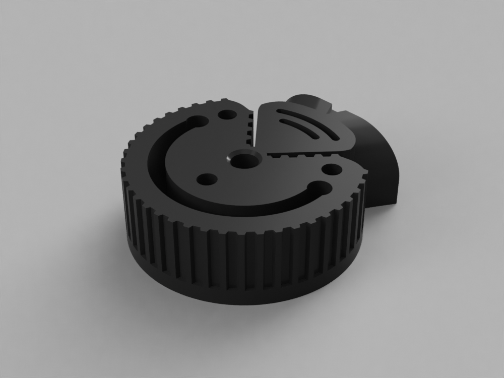 Wrist Half Quantity: 1 |
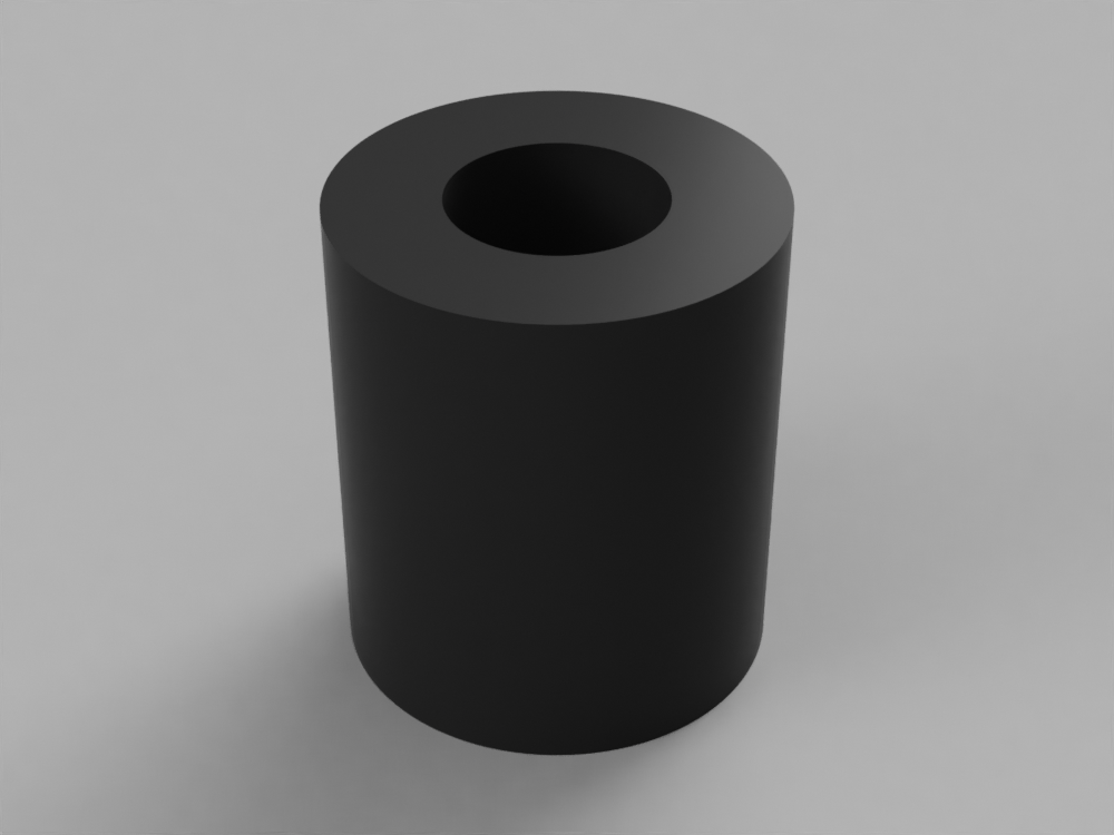 Cylinder Quantity: 2 | 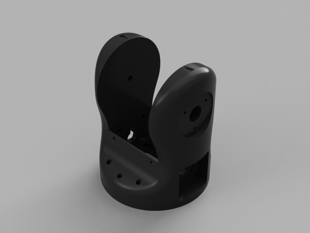 Shoulder Base Quantity: 1 | 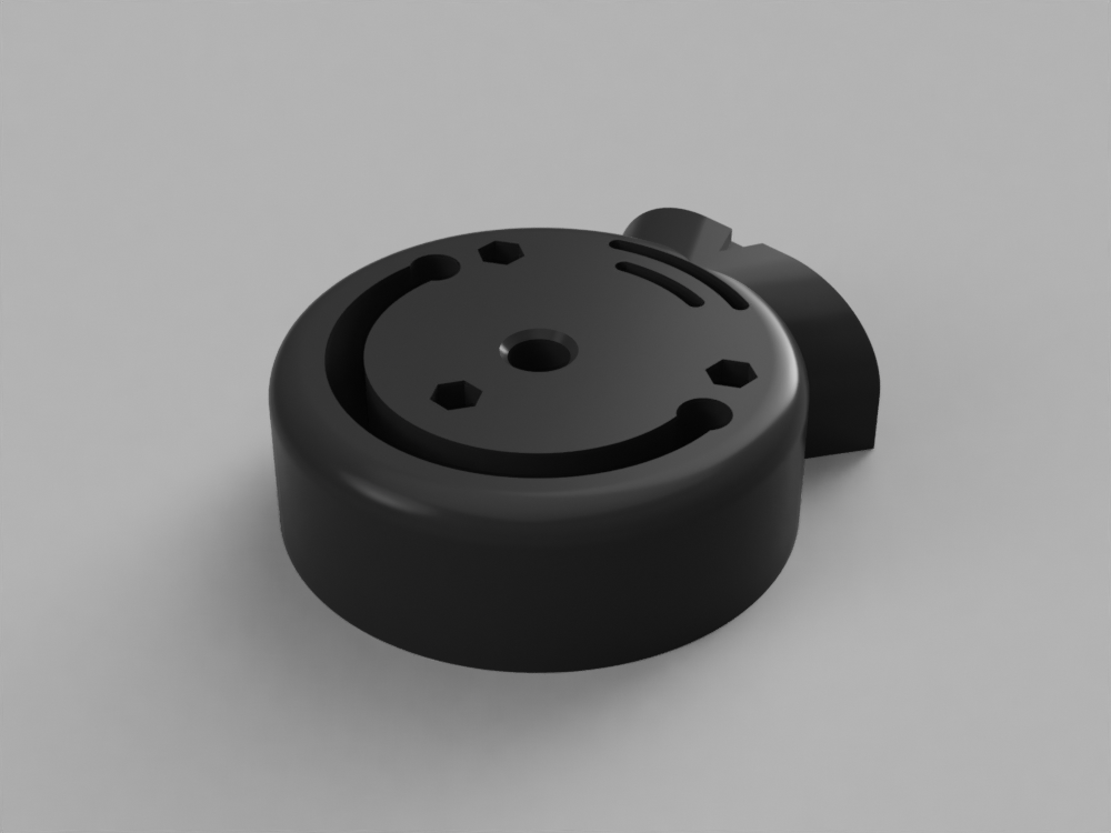 Wrist Half Quantity: 1 |
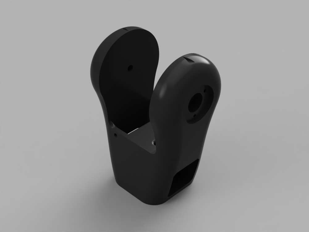 Elbow Base Quantity: 1 | 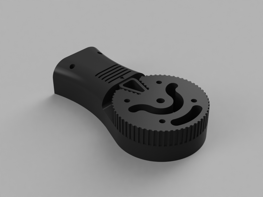 Elbow Joint Half Quantity: 1 | 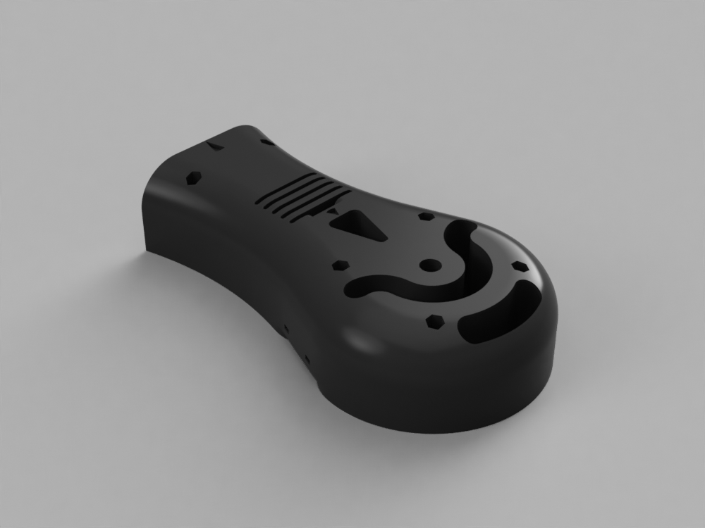 Elbow Joint Half Quantity: 1 |
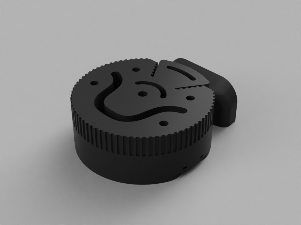 Shoulder Joint Quantity: 1 | 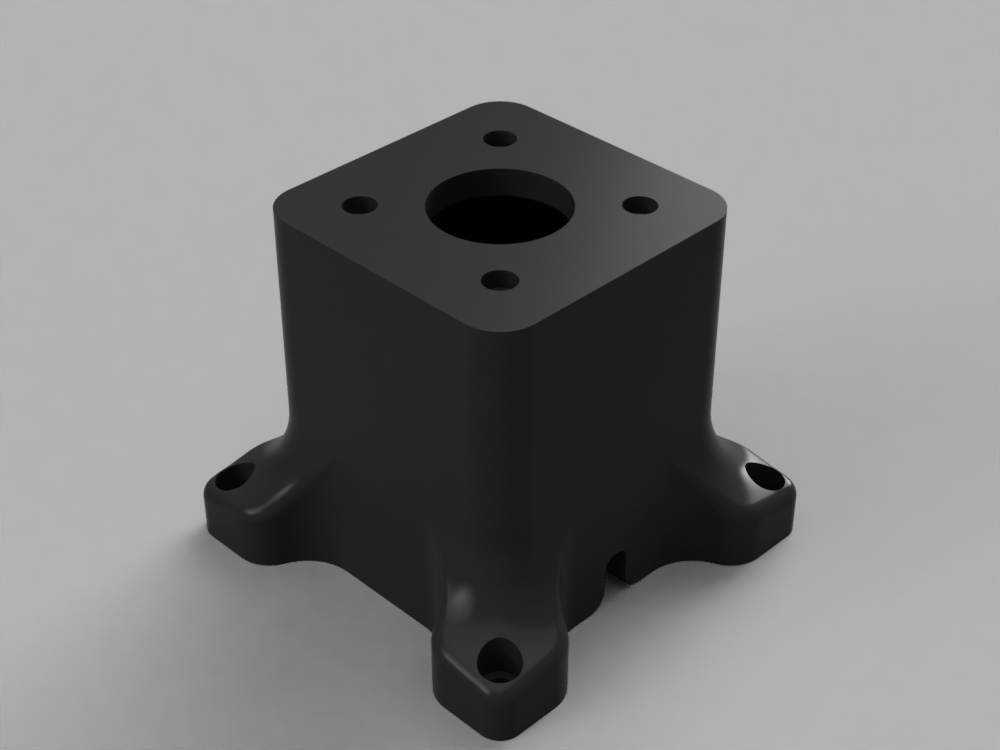 Base Motor Mount Quantity: 1 | 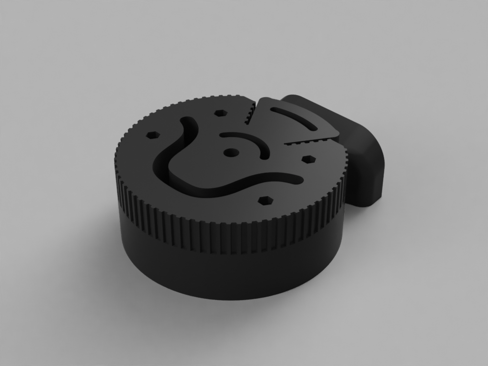 Shoulder Joint Quantity: 1 |
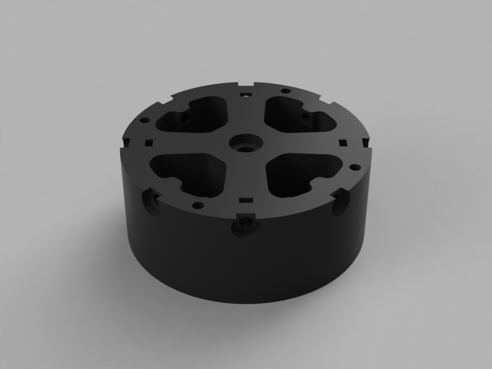 Rotary Base Quantity: 1 | 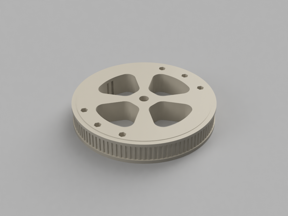 Rotary Plate Quantity: 1 |
Step 3: Install Heat-Set Inserts Into Rotary Base
Most parts of the robot arm connect together using heat-set inserts and machine screws. Heat-set inserts are a convenient and fast way to add threads to holes in a 3D printed part. Once pressed into place using a heat source, the brass inserts can be used to fasten together different parts to create strong connections.
To install the heat-set inserts, we will need a soldering iron, a pair of hemostats, and a way to hold the 3D printed covers steady. For this last piece of equipment, I am using a great helping hands tool from QuadHands.
To install the heat set inserts, warm your soldering iron to 230oC. Then, with the 3D printed part clamped in place, hold the heat-set insert with the hemostats just over the hole. Press the heat-set insert into the plastic part with the soldering iron. The heat from the soldering iron should melt the plastic, allowing the heat-set insert to set into the part. Try to work quickly to avoid applying too much heat and deforming the plastic surrounding the holes.

Because the M5 heat-set inserts are fairly large in terms of the amount of metal the soldering iron needs to melt, it can take a bit of time to get the insert hot enough to set into the plastic.
Step 4: Add 8mm Bearings to Rotary Base
To provide low-friction movement, we will install two ball bearings into the Rotary Base. Later on, a shaft will connect the Rotary Plate to the Rotary Base and these two bearings will allow it to rotate freely.
The ball bearings are designed to be press-fit into the Rotary Base. The holes the bearings go into are exactly the same size as the bearings. Therefore, in order to make the bearings fit, we will need to use a heat gun to soften the plastic enough for force the bearings to seat into the part.
Using a heat gun (like the extremely well documented Heaterizer XL-3000 from Sparkfun), warm up the vertical sizes of the cylindrical pocket on top of the Rotary Base. Once the plastic gets warm enough, it will start to get slightly more shiny. Then, press the bearing into the heated pocket. Allow the plastic to cool again. It will contract as it cools, locking the bearing in place.
Then, just repeat the process for the bearing on the underside of the Rotary Base.

Step 5: Attach Ball Bearings to Rotary Base
The robot arm rotates on top of the Rotary Base. In this step we will attach ball bearings to the Rotary Base that allow the arm to rotate smoothly. The ball bearings protrude slightly above the top of the Rotary Base.
Using M5 x 14mm screws, attach a 5mm ball bearing to each of the eight heat-set inserts around the periphery of the Rotary Base part. Tighten the screws enough that the ball bearings to do wiggle too much, but not so tight that the bearings are unable to move smoothly.

By the time you are done, the Rotary Plate should glide smoothly on top of the bearings. Note that in the video below I have already installed the heat-set inserts into the Rotary Plate, which we will do in the next step.
Step 6: Install Heat-Set Inserts to Rotary Plate
The Rotary Plate part will eventually attach rigidly to the base of the robot arm itself. In order to form the connection, we will use heat-set inserts, just like we are doing with most of the rest of the robot arm's parts. In this step we will install a total of six M4 heat-set inserts into the top of the Rotary Plate part.

The procedure for installing the heat-set inserts is the same as we used for the Rotary Base. Just use a soldering iron to carefully heat and press the inserts into place. The top of the inserts should be flush with the Rotary Plate.
Step 7: Assemble Base Motor
Next we will set the Rotary Base and Rotary Plate aside while we work on assembling the motor that will rotate the base of the arm into the enclosure that will hold it. This robotic arm project uses five different kinds of stepper motors to move various parts of the arm. For the base of the robot, we will use a Nema 17 motor with a body length of 60mm.
To assemble the base motor, insert the Nema 17 x 60mm motor into the 3D printed Base Motor Holder component. On one side of the holder, there is a notch to hold the cable leads from the motor. Secure the motor in place with four M3 x 10mm screws.
Note that I am using a unipolar stepper left over from a different project so the motor in the images has six wires. The motor from the parts list on this Instructable is a bipolar stepper with four wires.

Step 8: Add Belt Pulley to Base Motor
With the base motor installed in its mount, now need to install the T5 belt pulley onto the motor that will drive belt used to move the Rotary Plate. The T5 pulley from BrecoFlex does not have a set screw. Therefore, we will glue the pulley in place instead.
So, apply a bit of thread locking compound into the pulley bore. Then, press the pulley onto the motor shaft with the narrower part of the pulley first. Hold the pulley in place for a few minutes until the thread locking compound cures enough to hold the pulley in place.

Step 9: Install Heat-Set Inserts Into Shoulder Joint
Next on our list of robot arm sub-assemblies to create is is the largest in this project, the robot arm's "shoulder." The shoulder, which is the base of the arm, houses two large, powerful Nema 23 stepper motors, belt tensioner, and the larges gear assembly in the arm, the Shoulder Joint we will begin assembling in this step.
The Shoulder Joint, like the other joints in this project, is built in two halves to make printing the parts much easier. We will join the two halves of the joint using heat-set inserts and machine screws.
In order to identify which half of the Shoulder Joint the heat-set inserts go into, look for the half with chamfered holes. Using the same technique we employed for installing the other heat-set inserts, install an M4 heat-set insert into each of the four holes on top of the Shoulder Joint half.

The trick to installing heat-set inserts into this part is that the heat-set insert will be set below the face of the part. When installing the inserts, be careful not to touch the 3D printed part itself with your soldering iron.
Step 10: Connect Shoulder Joint Halves
With heat-set inserts installed in one half of the shoulder joint, we can now join the two halves together. Simply place the two halves together and connect them using four M4 x 55mm screws.

Step 11: Install Heat-Set Inserts Into Shoulder Joint Assembly
There are four more heat-set inserts we need to install into the Shoulder Joint assembly now that we have the two halves of the assembly connected. These heat-set inserts, which we will install into the base of the part, will be used to connect the next joint assembly on the arm, the "elbow."
Again using the same technique that you are probably perfecting by now, install four M4 heat-set inserts into the base of the Shoulder Assembly.

Step 12: Add Belts to the Shoulder Joint
We are on to the last step in preparing the Shoulder Joint before moving on to other parts of the robot arm. The last thing to do is attach the T5 belts to the Shoulder Joint so they are ready for when we complete the shoulder assembly later on.
If you take a look at the Shoulder Joint part, you will notice that the teeth around the edge of the part extend into a groove that does down into the part.These groves will be used to lock the belt in place.
So, first of all, cut off two 36cm lengths of T5 belt. Then, with each belt, slide the ends into the slots in the Shoulder Joint. For now the belts will just be loosely hanging off the part.
Step 13: Install Heat-Set Inserts Into Shoulder Base
In this step we will install the heat-set inserts into the Shoulder Base necessary to attach all the other components.
First, near the base of the part on each side, you will be able to obviously determine where the Nema 23 stepper motors will be installed later on. Into each of the four holes, install an M5 heat-set insert.
Then, near the top of the part, install an M3 heat-set insert into each of the three holes in the circular cutout. Later on we will be installing a shaft into the top of this part that will form the middle of the shoulder joint. To hold the shaft in place, two 3D printed cover parts will be installed. The three M3 heat-set inserts on each side of the Shoulder Base part will be used to connect these covers in a later step.

Step 14: Install Two More Heat-Set Inserts Into Shoulder Base
In order to limit the complexity of the previous step, there are still two more heat-set inserts we need to install into the Shoulder Base part. These two inserts will be installed on the back side of the part.
As you can see in the videos in the Intro of this Instructable, most moving parts of the robot arm are driven by belts. For each belt in the robot arm, we will include a device for adjusting the tension on the belt. The two heat-set inserts we will install into the back of the Rotary Base in this step will later hold screws for adjusting the tension on the belt that moves the Shoulder Joint.

The heat-set inserts should be installed so that they are parallel to the bottom of the Rotary Base. In other words, when a screw is installed into the heat-set inserts, it should be horizontal.
Step 15: Assemble Base Belt Tensioners
In the previous step we installed the heat-set inserts that will later be used to adjust the tension on the belts for the Shoulder Joint part. In this step we will assemble the Base Belt Tensioners themselves.
These parts are fairly easy to put together. First, place three 4mm x 13mm x 5mm ball bearings. Then, insert an M4 x 20mm screw through the entire part. Finally, place a nut on the end of the screw. For this last part, you may need to break out the heat gun again and warm the plastic enough for the nut to slip into place.

Next, on the side of the Base Belt Tensioner 3D printed parts opposite the bearings we just assembled, you will notice a hexagonal spot. Using your heat gun, first warm up the plastic. Then, once the plastic becomes pliable, press an M3 nut into this spot.

Step 16: Install Base Belt Tensioners
In this step we will install the Base Belt Tensioners we just assembled. The tensioners mount inside the Shoulder Base part just in front of the two heat-set inserts we installed earlier.
First, if you look at the Shoulder Base part, inside the square pockets into which we will be installing the motors soon, you will notice a small hole next to the larger hole for the motor shaft. Simply insert an M3 x 25mm screw into each side of the Shoulder Base.

Next, to install the Base Belt Tensioners themselves, simply place each tensioner onto the screws and tighten them down. The two tensioners are mirrored parts. They should be installed such that the M3 nut is on the inside of the part.

Step 17: Add Nema 23 Motors to Shoulder Base
Now that all the necessary heat-set inserts have been installed into the Rotary Base, we can being adding the other parts of the assembly. First will be the two Nema 23 stepper motors. The motors should be oriented such that the wires protrude out the back of the Rotary Base, the same side on which the final two heat-set inserts were installed.
To install the motors, simply screw them in place using four M5 x 14mm screws.

Step 18: Add Belt Pulleys to Nema 23 Motors
With the two Nema 23 motors attached to the Shoulder Base, we can now install the two T5 belt pulleys. Like the pulley we installed on the base motor earlier, we will form the connection between the pulley and the motor shaft using thread locking compund.
First, apply a bit of thread locking compound into the pulley. Then, press the pulley onto the motor shaft with the narrow shank of the pulley closest to the pulley.

Step 19: Mount Shoulder Joint Onto Shoulder Base
In this step we will build the first of the robot arm's joints by mounting the Shoulder Joint onto the Shoulder Base. An 8mm x 140mm smooth rod will run through the middle of the Shoulder Joint, supported by two ball bearings in the Shoulder Base.
First, use your heat gun to warm up the plastic on the inside walls of the cutouts in the Shoulder Base that will house the bearings. When the plastic is warm enough to be flexible, press an 8mm x 22mm x 7mm ball bearing into each side of the part.

Next comes one of the trickiest parts of the build. We need to mount the Shoulder Joint onto the Shoulder Base by sliding a smooth rod through the bearings on either side of the Shoulder Base and through the Shoulder Joint while, at the same time, wrapping the belts around the pulleys on the motors.
The easiest way to do this is to first set the Shoulder Joint part inside the Shoulder Base so that the belts hang loosely out of the bottom of the Shoulder Base, then wrap the belts around the pulleys on the Nema 23 motors.
Finally, lift up the Shoulder Joint and insert the smooth rod through the middle.


Step 20: Insert Shoulder Belt Tensioner Screws
Now that the Shoulder Joint is mounted onto the Shoulder Base, the last step to completing the entire Shoulder is to add the screws for adjusting the tension on the belts. Compared to the previous one, this step is easy. Into each of the heat-set inserts behind the Base Belt Tensioners, insert an M4 x 20mm screw. Then, screw in each screw until the belt is tight enough that it does not slip on the pulleys when you manually move the Shoulder Joint, but not so tight that the Shoulder Joint is difficult to move. You can always fine-tune the tensioners later on.

Step 21: Attach Shoulder Shaft Covers
The smooth rod running through the Shoulder Base and supporting the Shoulder Joint will be held in place by a 3D printed cap on each side of the part. There are several different sizes of caps for this project, each one for a different joint on the robot arm. The ones for the Shoulder Joint are the largest.
To install the caps, simply place them in the holes on either side of the Shoulder Base and secure them in place with three M3 x 10mm screws.

Step 22: Install Heat-Set Inserts Into Elbow Base
At this point it is time to set the shoulder assembly aside and move on to the robot arm's next joint, the "elbow."
To begin assembling the elbow, we will go back to installing more heat-set inserts. The Elbow Base will need a total of seven heat-set inserts. Six of these will later be used to install the caps for holding the elbow smooth rod in place; the seventh will be used to adjust the Elbow Belt Tensioner.
First, on each side of the Elbow Base, install three M3 heat-set inserts into the large round holes just like we did for the Rotary Base part.

Now, to install the seventh heat-set insert, locate the small hole on the side of the Elbow Base. Install an M4 heat set insert. Just like with the Rotary Base part, the heat-set insert should be installed so that, once we put a screw into the insert, it will be parallel to the ground.

Step 23: Assemble Elbow Belt Tensioner
Next we will assemble the Elbow Belt Tensioner. This part is very similar to the Base Belt Tensioners we've already installed. Assembling the Elbow Belt Tensioner is similar as well.
The first step is to use a heat gun to worm the hexagonal hole for an M4 nut. Once the part becomes flexible, press the M4 nut into place.
Second, stack three 8mm x 22mm x 7mm bearings together and hold them in place with an M4 x 20mm screw.

Step 24: Add Elbow Belt Tensioner Nut
Installing the Elbow Belt Tensioner is another one of the more tricky parts of this build. If you take a look at the side of the Elbow Base with the hole for the motor, you will find a small hole above and to the right of the spot for the motor. In a couple minutes we will install a screw into this hole that will hold the belt tensioner.
First however, behind this hole you will find a spot for inserting a captive nut. Installing this nut is a little tricky because of its inaccessible location. The easiest way to install the nut is by using a screw as a handle for the nut. This way, we can use the heat gun to soften the plastic and press the nut into the hole.
Now we are ready to install the Elbow Belt Tensioner. However, before we do that, we need to connect the Elbow Base to the Shoulder Joint.
Step 25: Attach Elbow Base to Shoulder Joint
In this step we will unite the Elbow Base and the shoulder assembly. You've probably noticed that the elbow assembly is not yet complete because it is missing the motor. This is because the motor actually blocks two of the screws for connecting the Elbow Base to the Shoulder Joint so we need to connect these two parts first, and install the motor in the next step.
Four screws connect the Elbow Base to the Shoulder Joint. Position the Elbow Base so that the heat-set inserts on the back of the part, which will be used later for the Elbow Belt Tensioner, is on the same side as the corresponding part on the Shoulder Base. Then, connect the parts with four M4 x 10mm screws.

Step 26: Install Elbow Belt Tensioner
With the captive nut in place and the Elbow Base connected to the Shoulder Joint, we can install the Elbow Belt Tensioner without blocking any other parts we need to put together. Just place the Elbow Belt Tensioner into the slot in the Elbow Base, insert an M3 x 40mm screw through the Elbow Base and the belt tensioner, and screw it into the captive nut.

Step 27: Add Elbow Base Rod Bearings
The elbow joint is constructed basically the same way as the Shoulder Joint. The Elbow Joint will eventually be mounted onto a smooth rod running through the Elbow Base. In this step we will install ball bearings into the Elbow Base to allow the joint to operate smoothly.
The process for installing the ball bearings into the Elbow Base is the same as we used for the Shoulder Base ball bearings. First we need to warm up the hole for the bearings with the heat gun until the plastic is soft enough to insert the bearings.

Step 28: Install Elbow Motor
Now that the Elbow Base is connected to the Shoulder Joint, we can install the elbow motor without it getting in the way of other parts we still need to assemble. The motor used for the shoulder joint is the one with a built-in 5:1 gearbox. Because the elbow is low enough on the robot arm that it still needs to move the fairly heavy load of the rest of the arm, we need quite a bit of torque for this joint. The gearbox gives the elbow motor a mechanical advantage for moving the rest of the arm, without using multiple motors which would add a great deal of weight and size.
Installing the elbow motor is simple. Just insert the motor into the left side of the Elbow Base. Then, secure it in place with four M3 x 10mm screws.

Step 29: Add Belt Pulley to Elbow Motor
Next up we need to install a belt pulley onto the elbow motor. This is done the same was that we installed the belt pulleys onto the shoulder motors. First, apply a bit of thread-locking compound onto the pulley bore. Then, press the belt pulley onto the elbow motor shaft until it lines up with the Elbow Belt Tensioner.

Step 30: Install Heat-Set Inserts Into Elbow Joint
The next sub-assembly to put together and later attach to the rest of the robot arm will be the Elbow Joint. The Elbow Joint has the gear to be driven by the motor we just installed into the Elbow Base. Additionally, the Elbow Joint contains the motor that drives the "wrist."
The first step in assembling the Elbow Joint, just like with the other sub-assemblies, will be to install heat-set inserts into the part. Like with the Shoulder Joint, the Elbow Joint is made in two pieces. The heat-set inserts will be installed into the half without the teeth for the belt.
A total of six M3 heat-set inserts are needed for the Elbow Joint. The process for installing the inserts is basically the same as all the other inserts before with one difference: rather than removing the soldering iron when the heat-set insert is flush with the surface of the part, for the Elbow Joint heat-set inserts, keep applying pressure to sink the inserts at least 6mm below the surface of the part.

Step 31: Mount Wrist Motor 1 Into Elbow Joint
If you take a look at the insides of the Elbow Joint halves, you will notice a square pocket. This pocket will hold the motor that drives the twisting "wrist" joint that we will soon start building. On the Elbow Joint half with the belt teeth, you will find two holes on the end of the part. These holes will be used to mount the wrist motor into the part. In front of the pocket for the motor there is a smaller half-cylindrical pocket. This pocket will hold a shaft coupler that connects the motor shaft to the 8mm threaded rod used for the wrist joint. At the end of the 3D printed part, there is a small pocket for a ball bearing.
Before mounting the motor into the Elbow Joint, we need to attach the shaft coupler and the 8mm shaft to the motor. The shaft coupler has a 5mm hole on one side and an 8mm hole on the other. Attach the shaft coupler to the motor with about a 2mm gap between the coupler and the motor body. Tighten the set screws to hold the coupler in place.
Next, insert an 8mm x 40mm threaded rod into the shaft coupler and tighten down the other set screws to hold the rod in place.

Now we can install the motor itself into the Elbow Joint. To do this, simply place the motor assembly into the rectangular cutout in the Elbow Joint with the motor wires facing upwards. If the shaft coupler does not fit correctly, you may need to adjust its position on the motor shaft.
Then, place an 8mm x 22mm x 7mm ball bearing onto the 8mm threaded rod. And finally, to fasten the motor to the Elbow Joint, use two 3mm x 10mm screws inserted from the end of the Elbow Joint part.

Step 32: Connect Other Elbow Joint Half
With the wrist motor assembly mounted into one half of the Elbow Joint part, we can now attach the other half of the Elbow Joint to complete this sub-assembly. Thanks to the heat-set inserts we installed earlier, this process is easy.
The first thing to do is deal with the wires coming from the wrist motor. On the Elbow Joint half we will be installing in this step there is a hole for the stepper wires to run through. First thread the cables through this hole.
Then, simply place the two halves of the Elbow Joint together and, using six M3 x 50mm screws, connect the two parts together.

Step 33: Add Belt to Elbow Joint
Just like we did with the Shoulder Joint, we need to add the T5 belt to the Elbow Joint before mounting it onto the Elbow Base. Installing the belt is simple. If you take a look at the Elbow Joint, you will see that the tooth profile running around the periphery of the part extends towards the center of the part at the base of the Elbow Joint. Press one end of a 46cm lengh of T5 belt into one side of the Elbow Joint. Then, wrap the belt around the part and connect press the other end of the belt into place. For now the belt will hang loosely off the part.
Step 34: Mount Elbow Joint Onto Elbow Base
Now that the Elbow Joint is completely assembled, including the T5 belt, we can mount the part onto the Elbow Base. The process for doing this is very similar to when we mounted the Shoulder Joint onto the Shoulder Base.
First, set the Elbow Joint part inside the Elbow Base without inserting the smooth rod. There should be enough slack in the belt to wrap it around the pulley on the motor. Once the belt is in place, lift the Elbow Joint part into its final position, with the hole in the center of the part lining up with the ball bearings on either side of the Elbow Base. Finally, place an 8mm x 115mm smooth rod through the entire assembly.

Step 35: Attach Elbow Shaft Covers
To hold the smooth rod in place and finish the Elbow sub-assembly, we will add a cover to each side of the Elbow Base. Of the four covers remaining, the ones for the Elbow are the bigger ones.
Installing the Shaft Covers is simple. Place each cover into the round cutouts on either side of the Elbow Base and fasten them in place with three M3 x 10mm screws each.

Step 36: Install Heat-Set Inserts Into Wrist Base
With the elbow part of the robot arm complete, it is now time to start building the "wrist." Assembling the wrist will follow a similar process to the two joints we've assembled so far. The first step is to install heat-set inserts into the part.
A total of nine M3 heat-set inserts will be needed for the Wrist Base. The first six of these inserts will be used later on to attach the smooth rod covers to the part. On each side of the Wrist Base, install three M3 heat-set inserts into the holes for the rod covers.

Next we will install the remaining three heat-set inserts into the back of the part. One of the installs into the hole leading into the rectangular cutout in the center of the part. This hole will hole the screw for adjusting the Wrist Belt Tensioner. The design of the belt tensioning system on the wrist is just like the one used for the shoulder and for the elbow.

The final two heat-set inserts will be used for the cover near the bottom of the part. Soon we will be installing a ball bearing into the bottom of the Wrist Base to connect it to the Elbow Joint part. The next two heat-set inserts will later be used to install the cover that will hold this ball bearing in place.

Step 37: Add Ball Bearings to Wrist Base
Next we will add the two ball bearings to the Wrist Base that will later be used for the Wrist Joint sub-assembly to pivot smoothly. Installing these two ball bearings is just like installing the ones on the Shoulder Base and the Elbow Base.
Use your heat-gun to gently warm up the plastic inside the pockets for the ball bearings on the Wrist Base. When the plastic becomes pliable, press an 8mm x 22mm x 7mm ball bearing into each side of the Wrist Base.

Step 38: Mount the Captive Nut for the Wrist Belt Tensioner
The Wrist Base part, just like all of the other joints, has a belt tensioner to adjust the tension on the belt that drives the Wrist Joint. Like the belt tensioner for the Elbow Base, installing the captive nut used to hold the Wrist Belt Tensioner in place is a little tricky because of its inaccessible location. We will use the same technique in this step that we used to install the captive nut for the Elbow Base.
Warm up the cutout for the captive nut with your heat gun. Then, with the nut placed on the end of an M3 screw, press the nut into the cutout. After waiting for the plastic to cool and lock the nut in place, remove the M3 screw.
Step 39: Assemble Wrist Belt Tensioner
With the captive nut for installing the Wrist Belt Tensioner in place, we need to assemble the Wrist Belt Tensioner itself. This part looks basically the same as the other belt tensioners we've assembled already. The bearings for the Wrist Belt Tensioner are smaller than the others though.
First, using your heat gun, warm up the hexagonal hole on one side of the belt tensioner 3D printed part. When the plastic softens, press an M3 nut into the hole.
Next, stack three of the little 3mm x 10mm x 4mm ball bearings into the middle of the belt tensioner. Hold the assembly together with an M3 x 20mm screw.

Step 40: Install Wrist Belt Tensioner
Installing the Wrist Belt Tensioner is a fairly easy process, the only possible complication is the small size of the parts involved. To install the Wrist Belt Tensioner, place it inside the Wrist Base part, lining it up with the captive nut we installed earlier. Then, use an M3 x 20mm screw to hold the belt tensioner in place.

Step 41: Mount Wrist Motor 2
There is only one stepper motor left to install, the smallest of the lot, the Nema 14 stepper motor. The motor mounts into the Wrist Base part on the side opposite the belt tensioner. If you take a close look at the part, you will notice a small cutout on the bottom of the part. This cutout is used for the wrist motor wires.
To mount the wrist motor into the Wrist Base simply place it into the square cutout and secure it in place with four M3 x 10mm screws.

Step 42: Connect Wrist Base and Elbow Joint
Now that the Wrist Base sub-assembly is almost complete, it is time to unite the Wrist Base and Elbow Joint. The Wrist Base mounts onto the 8mm threaded rod sticking out the top of the Elbow Joint part.
First, if you take a look at the back of the Wrist Base part, you've probably already noticed a kind of "T" shaped hole. We will install two parts into this hole that will be used to form the connection between the Wrist Base and the Elbow Joint. First, in the wider part of the hole, insert an 8mm x 22mm x 7mm ball bearing. Press the bearing into the hole until the bore lines up with the 8mm hole on the bottom of the Wrist Base. Next, in the smaller part of the "T" shaped hole, on top of the bearing, insert an M8 lock nut.
With the bearing and the lock nut installed, screw the Wrist Base onto the threaded rod from the Elbow Joint. Tighten down the Wrist Base as much as you can until the wrist motor starts turning along with the Wrist Base, preventing the part from getting any tighter.

Step 43: Attach Wrist Back Cover
As the finishing touch that will complete the connection between the Wrist Base and the Elbow Joint, in this step we will add a cover to hide the ball bearing and lock nut inside the Wrist Base. This cover fits over the "T" shaped hole in the back of the Wrist Base.
To connect the cover, simply screw it in place using two M3 x 10mm screws.

Step 44: Add Belt Pulley to Wrist Motor
With the wrist motor installed, we need to add a belt pulley to drive the Wrist Joint. Just like the other motors, start by applying some thread lock compound into the belt pulley bore. Then, press the belt pulley onto the motor shaft so that the pulley lines up with the Wrist Belt Tensioner.

Step 45: Install Heat-Set Inserts Into Wrist Joint Half
The Wrist Joint sub-assembly is basically just a smaller version of the Shoulder Joint we built a while ago now. Assembling the Wrist Joint is easy. In this step we will install the heat-set inserts necessary to assemble the joint and connect it to the gripper later on.
There are a total of seven M3 heat-set inserts to be installed into the Wrist Joint parts. The first three heat-set inserts will be used to fasten the two halves of the Wrist Joint together. These heat-set inserts will be installed into the half of the Wrist Joint without teeth for the belt. We will use the same technique here that we used for the Elbow Joint to install the heat-set inserts below the surface of the part.

Step 46: Fasten Together Wrist Joint Halves
With heat-set inserts installed into one half of the Wrist Joint, now we can fasten the two halves together. This step is an easy one. Simply line up the two halves and then use three M3 x 25mm screws to connect them to each other.

Step 47: Install Heat-Set Inserts Into Wrist Joint Bottom
Now that the two halves of the Wrist Joint have been united, the final four M3 heat-set inserts can be installed. These inserts will be used later on to connect the gripper to the Wrist Joint. They install into the base of the Wrist Joint.

With the last of the heat-set inserts installed into the Wrist Base, the Wrist Joint sub-assembly is now complete.
Step 48: Add Belt to Wrist Joint
Next we will add a belt to the Wrist Joint that will later be used to move the joint. Attach an 18mm length of T5 timing belt to the Wrist joint the same way we attached belts to the Shoulder Joint and to the Elbow Joint, by pressing the ends of the belts into the sections of the tooth profile that extend towards the center of the Wrist Joint. Just like the other joints, the belt will hang loosely off the Wrist Joint.
Step 49: Mount Wrist Joint Onto Wrist Base
With the Wrist Joint sub-assembly complete, we will now work on mounting the Wrist Joint onto the Wrist Base. Again the first step is to place the Wrist Joint into the Wrist Base and wrap the T5 belt around the pulley. With the belt in place, lift the Wrist Joint into its final position and secure it in place by inserting an 8mm x 80mm smooth rod.

Step 50: Attach Wrist Shaft Covers
Now, to hold the shaft in place inside the Wrist Joint, we will again attach a 3D printed cover piece to each side of the Wrist Base. At this point in the build, there are only two shaft covers left. Attach one cover to each side of the Wrist Base, using three M3 x 10mm screws on each side to hold the covers in place.

Step 51: Insert Wrist Belt Tensioner Screw
The very last part to be installed in the Wrist section of the robot arm before it is complete is the screw used to adjust the tension on the belt. This step is a very simple one. The screw for adjusting the Wrist Belt Tensioner threads into the heat-set insert located behind the Wrist Belt Tensioner itself. Just screw an M3 x 20mm screw into this heat-set insert and tighten it until the belt reaches the appropriate tension.

Step 52: Install Heat-Set Inserts Into Gripper Bottom Plate
It's time to move on to the next part of the robot arm, the gripper. Our robot arm will be able to grab and move things using a servo-powered gripper on the end of the arm. In this step we will begin the process of assembling the gripper.
As with all the other sub-assemblies that make up the robot arm in this Instructable, the process of assembling the gripper begins by installing heat-set inserts. In this step we will install heat-set inserts into the Gripper Bottom Plate. We will install a total of five M3 heat-set inserts into the Gripper Bottom Plate. The inserts install into the part from the side with the cylindrical standoffs we will later use to connect the servo.

Step 53: Add Screws to Gripper Top Plate
We will now set the Gripper Bottom Plate aside for a moment and instead work on the Gripper Top Plate. The gripper is a fairly complex assembly of quite a few different parts. The first parts we need to install are the screws that will hold all of the other parts, as well as some washers that go on those screws.
We need a total of six M3 x 16mm screws. If you take a look at the inside of the Gripper Top Plate, you will find eight holes. However, only six of the holes are countersunk. The six screws go into the countersunk holes.
Then, on the other side of the Gripper Top Plate, place a washer on the four screws on the outsides of the Gripper Top Plate.

Step 54: Add Gripper Motion Parts and Spacers
Moving on with the Gripper assembly, in this step we will add a few more of the parts that will ultimately end up sandwiched between the Gripper Top Plate and Gripper Bottom Plate. First, the Gripper uses four arms extending from the center of the body to the gripper jaws. This system of two arms per jaw ensures that the jaws are always parallel to each other. Two of the arms are geared, allowing a single motor to move both jaws simultaneously.
In this step we will add three of the four arms to the Gripper assembly - the fourth arm is slightly more complex than the others. First, the two 3D printed spacer parts mount onto the two screws in the middle of the Gripper assembly. There are two identical non-geared arms that install on the two screws on the front of the Gripper Top Plate that are spaced closer together than the other screws.
Finally, there are two arms with gear teeth. One has one hole in the middle and the other has three holes in total. In this step we will add the geared arm with only one hole. If you are looking at the Gripper Top Plate with the screws sticking up towards you, the geared arm goes onto the screw on the left. The gears should face the front of the Gripper.

Step 55: Install Heat-Set Insert Into Gripper Gear Arm A
We have one arm left to install into the Gripper assembly. This is the arm that will be driven by the servo motor we will be mounting onto the Gripper assembly later on. In this step we will install a heat-set insert into the Gripper Gear Arm A that will allow the arm to be connected rigidly to the servo motor.
We will use the same technique to install an M3 heat-set insert into the Gripper Gear Arm A that we used for all of the many other heat-set inserts we've been installing throughout this Instructable. The heat-set insert should be installed from the side of the gear depicted in the images attached to this step.
Step 56: Add Final Gear Arm to Gripper Assembly
Now that we've installed a heat-set insert into the final arm for the Gripper Assembly, we can now add the arm to the rest of the Gripper Assembly, First, apply a bit of thread locking compound to the heat-set insert in the last geared arm. Then the arm simply screws onto the only open screw left on the Gripper Top Plate. When installing the arm, position both of the geared arms so that the arms themselves are co-linear.
Once you have the final arm installed, also add a washer on top of the other three arms.

Step 57: Attach Gripper Bottom Plate
With all of the arms and other components installed inside the Gripper assembly, we can now add the Gripper Bottom Plate we installed heat-set inserts into earlier. Simply place the Gripper Bottom Plate onto the rest of the assembly. Tighten all of the screws until the Gripper assembly does not wiggle or twist, but not so much that the arms are prevented from moving smoothly.

Step 58: Install Heat-Set Inserts Into Gripper Jaws
The Gripper has two opposing jaws controlled by a servo motor. The jaws connect to the ends of the arms we've already installed. We will again use heat-set inserts and screws to form the connection. So, in this step, install two M3 heat-set inserts into each of the jaws.

Step 59: Connect Jaws to Gripper Assembly
With heat-set inserts installed in the gripper jaws, we can now connect the jaws to the gripper arms. After the jaws are installed, the flat side of the jaws will meet when the jaws close. Connect the jaws to the gripper arms using M3 x 16mm screws. Like with the arms themselves, the screws should be tight enough that the jaws are not loose, but not so tight that they bind.

Step 60: Attach Gripper Assembly to Wrist Joint
The Gripper assembly is not quite complete yet; we still need to add the servo motor. However, before we can do that, we need to attach the Gripper to the Wrist Joint because the servo will block two of the screws we need to do that. Therefore, we will attach the gripper to the robot arm in this step and add the servo in the next step.
The Gripper attaches to the Wrist Joint using the four heat-set inserts on the top of the Wrist Joint. Place the Gripper on the Wrist Joint with the heat-set inserts facing the side of the Wrist Joint with the cover for the ball bearing. Connect the Gripper using four M3 x 10mm screws.

Step 61: Drill Center Hole in Base
At this point, the robot arm itself is basically complete, congratulations! Now we can begin working on the base onto which the robot arm will eventually be mounted. The base consists of a wooden platform on legs. The Rotary Base we assembled long ago, at the beginning of this Instructable, will soon be mounted onto the base.
In this step we will begin preparing the base. If you have not done so already, cut a square piece of 3/4 inch plywood measuring 16 inches on each side. The first step in preparing the base is to drill a hole in the middle of the base. The entire robot arm will attach to the base via an M8 bolt. The hole in the middle of the base will allow the locknut on the base to be tightened from underneath the platform.
So, measuring corner-to-corner, figure out were the exact center of the base is located. Drill a 1in hole into the wooden platform.
Step 62: Drill Rotary Base Mounting Holes
Now that we have a hole in the wooden platform for accessing the M8 locknut for the Rotary Plate shaft later on, we can drill mounting holes for the Rotary Base. I find that the easiest way to do this is empirically. First, place the Rotary Base onto the wooden platform so that the ball bearings line up with the hole we just drilled in the wooden platform. Then, using a long 4mm drill bit, drill down through the Rotary Base and into the wooden platform. The Rotary Base has a total of four mounting holes.
Step 63: Drill Base Leg Mounting Holes
We will use the same technique we just used to add mounting holes for the Rotary Base to add mounting holes for the Base Legs. One leg mounts on each corner of the wooden platform. Again using a long 4mm drill bit, position a leg on each corner of the platform, then drill down through the leg to create a mounting hole.
Step 64: Install Heat-Set Inserts Into Base Legs
Next we need to install heat-set inserts into the Base Legs for attaching them to the wooden platform, which we will do in the next step. One M4 heat-set insert installs into each of the Base Legs. The inserts install from the top side of the legs.
Step 65: Attach Base Legs to Wooden Platform
With heat-set inserts installed into each of the Base Legs and mounting holes drilled into the wooden platform, we can now attach the Base Legs. First place the legs under the platform. Place a washer onto four M4 x 40mm screws. Then, use the screws to attach the legs to the platform. The screws merely need to be snug to hold the legs in place. Keep in mind that the weight of the robot arm will effectively be working with the screws to hold down the wooden platform.
Step 66: Attach Rotary Base to Wooden Platform
Next we will work on mounting the Rotary Base onto the wooden platform. The first step is to add the mounting screws to the Rotary Base. Insert four M4 x 55mm screws into the four mounting holes around the outer part of the Rotary Base.
Then, if you take a look at the mounting holes on the Rotary Base, you will noticed that they are arranged in a rectangular pattern; note that they are not evenly spaced around the Rotary Base. Therefore, the Rotary Base needs to be mounted to the wooden platform in a specific orientation. Place the Rotary Base onto the wooden platform with the mounting screws protruding through the platform and out the bottom.
Finally, secure the Rotary Base in place using a washer and nut on each of the mounting screws.
Step 67: Add Shaft for Rotary Plate
With the Rotary Base in place, we can start getting ready to add the Rotary Plate to the assembly. As we saw long ago when we were assembling the two parts, the Rotary Plate rotates on top of the Rotary Base. In this step we will add an M8 x 65mm screw to the Rotary Plate that will act as the rotational shaft and connect the Rotary Plate and Rotary Base together.
On the side of the Rotary Plate with the heat-set inserts, you will notice that in the middle of the part there is a hexagonal cutout for the head on the M8 bolt. To install the Rotary Plate shaft, simply press an M8 x 65mm bolt into the hole in the middle of the piece.
Step 68: Add a Belt to the Rotary Plate
Next we will install the timing belt onto the Rotary Plate. The belt installs the same way as all the others. The Rotary Plate is ringed by a tooth profile for the T5 belt. The tooth profile extends into the center of the plate. Place the ends of a 65cm length of T5 belt into the tooth profiles that extend towards the center of the Rotary Plate.
Step 69: Mount the Rotary Plate Onto the Rotary Base
With the Rotary Plate shaft and timing belt in place, in this step we can mount the Rotary Plate onto the Rotary Base. First, place the Rotary Plate onto the Rotary Base with the M8 bolt inserted through the ball bearings in the Rotary Base. Then, insert an M8 locknut through the hole in the center of the wooden base. A normal socket wrench is the best tool to tighten the locknut onto the M8 bolt.
Step 70: Mount Base Motor Onto the Base
As with the Rotary Base, the easiest way to attach the base motor to determine its location empirically. First, if you take a look at the Rotary Base and the Rotary Plate, you will notice that each part has a small triangle on one side. Rotate the Rotary Plate until the two triangles on the parts match up.
The base motor does its job best when it is mounted on the side of the Rotary Base opposite the two small triangles that are now lined up. Place the motor assembly onto the wooden platform with the Rotary Plate belt wrapped around the pulley on the motor.
Adjust the position of the belt motor until the belt is tight enough to avoid slipping but not so tight that the motor can't move the Rotary Plate. Just like with the Rotary Base and Base Legs, the easiest way to figure out where to drill the mounting holes for the motor is to drill them through the part while it is in the correct position. So, with the base motor positioned where you want it, drill four holes through the mounting holes in the Base Motor Holder.
Finally, secure the base motor in place using four M4 x 45mm screws, with washers and nuts on the underside of the wooden platform.
Step 71: Mount Robot Arm Onto Rotary Base
We are now on to a fairly exciting step. It is time to mount the robot arm assembly onto the Rotary Plate. This will complete the entire arm assembly! After this step, all we will have left to do is mount the Arduino board, wire everything to the Arduino, program the Arduino, do some cable management, and get the arm moving.
Mounting the robot arm onto the Rotary Plate is not too difficult. One thing to be mindful of while mounting the robot arm onto the base assembly is that there is nothing really preventing the robot arm from tipping over at this point. Be careful not to let the arm fall because it is long and heavy enough that damage would likely result from the arm hitting a table.
The robot arm mounts onto the Rotary Base using six M4 x 40mm screws that will thread into the heat-set inserts we installed into the Rotary Plate long ago. So, simply place the robot arm onto the Rotary Plate with the six holes aligned. Then, fasten the robot arm down using M4 x 40mm screws.
Step 72: Route Wrist and Elbow Motor Cables
After this much time working on the robot arm, you've probably noticed a couple small cutouts on the back side of the Shoulder Joint and Elbow Joint parts. These are for doing the first bit of cable management. In order to avoid having cables fall into the joints and getting tangled or cut, we will use the cutouts to hold the wires away from the joints.
First, place a zip-tie through the two small slots on either side of each cutout. Eventually we will tighten the zip-ties into loops to hold the wires in place. Then, simply place the wires into the cutouts and tighten the zip-ties to hold the wires in place.
Step 73: Assemble Controller
The controller for the robot arm consists of several parts:
- For the controller itself, we will be using an Arduino Mega 2560.
- To allow the Arduino to interface with the motors on the robot arm, we will use a RAMPS shield. The RAMPS shield is normally used as part of the control electronics for 3D printers. 3D printers use several stepper motors for movement just like the robot arm, so the RAMPS shield works great for controlling the robot arm as well.
- Finally, we will equip the RAMPS shield with DRV8825 stepper drivers. Several of the stepper motors on the robot arm are substantially larger than those used on a 3D printer. So, instead of the drivers normally used for a 3D printer, we will use DRV8825 drivers for this project because they can handle much higher currents than other more common drivers.
Assembling the control electronics is not overly difficult. First, place the RAMPS shield onto the Arduino Mega and apply firm pressure to connect the two boards. The RAMPS shield should be oriented with the power screw terminals on the same side as the USB port on the Arduino.
With the RAMPS shield mounted onto the Arduino board we now need to add the DRV8825 stepper drivers. If you take a look at the driver modules, you will notice a little screw trim pot on one side. When mounting the stepper drivers onto the RAMPS board, the modules should be oriented with the trim pot closest to the RAMPS shield power screw terminals.
Step 74: Mount Controller Onto Base
With the controller assembled, we now need to mount it onto the wooden platform. You can mount the controller anywhere you think it looks good. I mounted mine next to the base motor.
We will use a similar technique for mounting the controller that we used for the other parts on the Base. First place the controller where you want it to be mounted. Then, very carefully drill down through the two mounting holes and into the wooden platform. Just starting the holes to establish an accurate location for them would be enough, you can finish drilling through the plywood after removing the controller.
With the controller in place, attach it to the platform using two M4 x 40mm screws and two M4 nuts.
Step 75: Extend Motor and Servo Cables
The motor cables coming from the wrist portion of the robot arm are not long enough to reach the controller. Therefore, in this step we will solder longer cables onto the wires so that we can connect them to the controller in the next step. There is nothing fancy to do here, simply solder an extra 50cm of wire onto each cable. Apply a bit of shrink-wrap tubing onto the solder joints to protect them and prevent short circuits.
Step 76: Add Pin Headers to Motor Cables
Next we need to add headers to the ends of the cables so they can be connected to the RAMPS shield in an upcoming step. Connecting headers to the wires is done using crimp pins and a crimping tool. If you've never used a crimp tool before, it is an extremely useful skill to have, because it will allow you to create custom jumper wires whenever you need them. Inventables has a great blog post that explains how to use a crimp tool to install crimp pins.
All but one of the stepper motors will be wired the same way. For the two wrist motors, the elbow motor, the base motor, and only one of the shoulder motors, install a 4-pin header and housing onto the end of each stepper motor cable. When inserting the wires into the pin housings, the order of the cables should be black, green, red, blue.
The reason we only wired one of the shoulder motors with the wiring order above is because if we had wired both shoulder steppers that way, when facing each other they would have turned in opposite directions. This is obviously a bad thing because the Shoulder Joint would not move because it would be pulled equally in both directions. Therefore, we need to change the wiring order for one of the stepper motors. For a detailed explanation of stepper motor wiring, the RepRap Wiki page on stepper wiring makes for good reading. Essentially we will be reversing one of the motor coils to get the motor to turn in the opposite direction with the same drive signal.
So, for the second shoulder motor, the wiring order should be green, black, red, blue. By reversing the black and green wires, which are connected to one coil pair in the motor, the two shoulder stepper motors will now turn in opposite directions when given the same drive signal. Because of the way they are mounted onto the robot arm, this means the two motors will work together to move the Shoulder Joint.

We will also need a 3-pin housing on the servo cable.
Step 77: Wrap Cables
In order to tidy up all the cables and reduce the chance that any of them will end up tangled or caught in any of the robot arm's joints, we will wrap the wires to bind them together. There are several different types of wire wraps. For this project I like to use a spiral-wrap cable management product because the spiral-wrap types are more flexible than split tube types. The cord wrap I use in this Instructable is one from Amazon.
Step 78: Wire the Robot Arm
With the controller in place, the motor cables prepared, and connectors attached to all the wires, we can finally connect all the motors to the RAMPS shield. When connecting all of the stepper motors, keep in mind that the blue wire will always be closest to the side of the RAMPS shield with the power screw terminals.
First, since both of the shoulder motors will work together to move the arms, they will be connected to the same motor driver. Since the only motor driver on the RAMPS shield with two sets of connections is the Z-Axis driver, the shoulder motors will connect to that driver. With the blue wire closest to the power screw terminals, connect the two shoulder motors to the pins next to the Z-Axis stepper driver.
Second, connect the elbow motor to the Y-Axis stepper driver, again with the blue wire closest to the power screw terminals.
Third, connect the first wrist motor to the X-Axis motor driver.
Fourth, connect the second wrist motor to the E1 stepper driver. On a 3D printer, this driver would be used for moving the stepper motor that pushes filament into the hotend. For this project however, we will use the E1 driver as just another movement axis.
Finally, the last motor left to be connected is the servo motor on the gripper. Servo motors are not commonly used on 3D printers, but the RAMPS shield does have connectors for servo motors. If you take a look at the side of the board next to the yellow fuses and the reset button, you will find a set of servo connectors. Plug the gripper servo into the connector farthest from the power screw terminal.
Step 79: Mount Power Supply
There is only one part we still need to attach to the robot arm assembly, the power supply. The power supply will mount on the underside of the wooden platform. Soon we will route wires from the power supply to the RAMPS board and plug the power supply into a mains electrical supply.
The mounting holes on the power supply are arranged in a 50mm x 150mm rectangle. For the power supply, we will not be able to just place the part and drill holes empirically like we've been doing with the other parts. Mounting the power supply will involve measuring out the locations for the holes. So, draw a 50mm x 150mm rectangle on a piece of paper. Then, place the paper on the wooden platform and drill holes through the corners of the rectangle.
Then, place the power supply under the wooden platform and, using four M3 x 20mm screws. The screws should be just a bit longer than the wooden platform is thick.
Step 80: Wire RAMPS to Power Supply
With the power supply mounted, we can now connect the power supply to the RAMPS shield. There are several screw terminals on both the power supply and the RAMPS board.
On the power supply, there is a large screw terminal with four connection points, and a small screw terminal with two connection points. If you are looking at the power supply as it is mounted under the wooden platform, the terminal closest to the power plug is the positive connection. Connect a red wire to this terminal. The second connection from the plug is ground. Connect a black wire to this terminal.
Then, on the RAMPS shield, there is a bank of six screw terminals and a bank of four screw terminals. We need to connect the wires from the power supply to the bank of four screw terminals. The ground (black) wire connects to the terminal closest to the edge of the board. Then the positive (red) terminal connects to the next terminal.
Step 81: Tune Stepper Driver Current
Before we run the control code and get the stepper motors moving, we need to adjust the DRV8825 stepper drivers so that they deliver the correct current to each motor. The current delivered by each driver can be adjusted using the trip pots on each driver board.
First a bit of theory though. In order to determine the maximum current each stepper driver is set to deliver, we will measure the reference voltage between the trim pot and a ground pin using a multimeter. As we turn the trim pot, the reference voltage will change. Determining the reference voltage that corresponds to the current we want involves a very simple calculation:
Vref = 0.5Ω * Imax
Where Vref is the reference voltage measured between the trim pot and ground, and Imax is the maximum current the stepper driver will deliver.
Each of the stepper motors needs a different amount of current. Therefore, we will need to calculate the target reference voltage for each stepper driver. Then we just need to adjust the trim pots on each driver to get the desired reference voltage.
Nema 17 (base motor)
Maximum current rating: 1.2A
Running current: 1A
Vref = 0.5 Ω * 1A
Vref = 0.5V
Nema 23 (shoulder)
Maximum current rating: 2.8A
Running current: 2A
Vref = 0.5 Ω * 2A
Vref = 1V
5:1 Geared Stepper (elbow)
Maximum current rating: 0.4A
Running current: 0.3A
Vref = 0.5 Ω * 0.3A
Vref = 0.15V
Nema 17 (wrist)
Maximum current rating: 0.4A
Running current: 0.4A
Vref = 0.5 Ω * 0.4A
Vref = 0.2V
Nema 14 (wrist)
Maximum current rating: 0.8A
Running current: 0.6A
Vref = 0.5 Ω * 0.6A
Vref = 0.3V
To actually measure the reference voltage, clip one lead of the multimeter to a screwdriver used to adjust the trim pot. Attach the other lead to the ground pin on the driver board, which is the one in the corner of the board opposite the pin right next to the trim pot. The trim pot only turns about 180 degrees from one extreme to the other, so make only tiny adjustments to the trim pot until the desired reference voltage is reached.
Step 82: Program the Arduino
Finally, the last task to do before the robot arm will be operational is programming the Arduino Mega with the code needed to control the arm. The firmware for the robot arm is available on the GitHub page for this project.
The code used to control the robot arm is actually the Marlin firmware which is typically used for controlling 3D printers. Since, from a hardware perspective, a 3D printer is basically just a collection of stepper motors, just like the robot arm, the Marlin firmware works very well for controlling the robot arm in this Instructable. The Marlin firmware was adapted by BCN3D for use in this project.
The next step will cover more details on the actual commands used to move the robot arm in different ways.
Uploading the robot arm code to the Arduino Mega is done the same way as uploading any other sketch. First, open the Marlin.ino file in the Arduino IDE. Then, with the Arduino Mega connected to your computer via USB, press the upload button. The sketch is fairly large, so it will take a minute to finish uploading to the board.
Step 83: Controlling the Robot Arm With G-Code
Congratulations! It has been a lot of hard work, but the robot arm is finally ready to move! This step will explain how to control the robot arm to make it move where you want.
The robot arm is controlled using G-Code. G-Code is a type of programming language commonly used to tell computer-controlled machines how to make things. Almost every 3D printer and CNC machine on the planet takes G-Code commands during operation. The G-Code tells these types of machines how to move. The Arduino and RAMPS combination we are using to control the robot is normally used to control 3D printers. In essence, the Arduino/RAMPS/Marlin firmware combination is a platform for interpreting and executing G-Code.
We will use different G-Code Commands to move the different motors on the robot arm.
Shoulder Movement
| Command | Min | Max |
|---|---|---|
| G0 Znnn | 110 | -110 |
Elbow Movement
| Command | Min | Max |
|---|---|---|
| G0 Ynnn | 90 | -60 |
Wrist 1 Movement
| Command | Min | Max |
|---|---|---|
| G0 Xnnn | 90 | -60 |
Wrist 2 Movement
| Command | Min | Max |
|---|---|---|
| G0 Tnnn | 90 | -60 |
Base Movement
| Command | Min | Max |
|---|---|---|
| G0 Ennn | 90 | -60 |
Gripper
| Command | Min | Max |
|---|---|---|
| M280 | S5 (open) | S10 (closed) |

Participated in the
Robotics Contest 2017

Participated in the
Power Supply Contest

Participated in the
Design Now: In Motion Contest


