Introduction: Build an EMG Audio Amplifier! (Electromyography)
Whenever your body needs to make a movement, the nervous system sends out tiny electrical signals that control your muscles. The technique of electromyography (EMG) allows us to amplify and measure these electrical signals. In addition to being a useful clinical tool for diagnosing various neurological disorders, EMG recordings can be used for engineering projects such as controlling prosthetic devices or playing music. If you've watched the White Rabbit Project, you know that EMG signals can even be used to control someone else's arm!
This Instructable will walk you through the process of building an EMG amplifier that allows you to translate the tiny electrical signals produced by motoneurons into an audio signal played through speakers. These instructions are for making a two channel amplifier (i.e. listen to the activity of two muscles at once), but it's simple to make a single channel amplifier to save time and/or parts.
Sure, you can spend more money on a fancy pre-made MyoWare sensor, but why not save the money, learn a new skill, and build one yourself? Let's get started!
Background Knowledge
This Instructable includes breadboarding a circuit and soldering a few wires. If you don't have some of this necessary background, I recommend checking out the Electronics Instructables class.
Safety Note
This project does involve connecting oneself to an electrical circuit. We'll be powering our circuit off of two 9V batteries; at no point should your circuit (especially when you're connected to it) be connected to AC power from the wall. This paper from Delsys has a section on electrical safety as well as a useful description of EMG techniques in general.
Step 1: Parts and Tools
A particularly cool part of this project is that it's actually fairly cheap and easy to put together! The most important part of the system, the LT1167 instrumentation amplifier, only costs $7.32 on DigiKey. The type of surface electrodes aren't all that important and can be found for around $10 on Amazon. Instead of an expensive power supply, the whole system is powered off of just two 9V batteries wired in series. And if you're lucky, you'll have a lot of the other electrical components scattered around your work space!
Parts
(2x) LT1167 (instrumentation amplifier) (DigiKey)
(2x) LT1112 (or any dual op-amp chip) (DigiKey)
(1x) LM386N (audio amplifier) (DigiKey)
(1x) Audio jack (SparkFun)
(5x) Surface EMG electrodes (two per muscle and one for a reference) (Amazon)
Breadboard (Amazon)
Various resistors, capacitors, and jumper wires
(2x) 9V battery
Tools
Speaker with an auxiliary input + an 1/8" audio cable
Soldering iron
Wire strippers
Heat shrink tubing
Electrical tape
Step 2: Amplifier Concepts & Design
EMG signals are measured differentially, meaning the signal we amplify and analyze is actually the difference in electrical potential between two points on the muscle. I recommend the Wikipedia article on differential amplifiers for a more in-depth review of the topic, but I'll give a brief explanation here.
Our main goal with this EMG amplifier is to amplify the signal we're interested in (muscle activity) without increasing the noise (often from external electrical interference). A differential amplifier operates on the assumption that any noise signal interfering with our EMG recording will uniformly affect the local region of muscle we're recording from. In other words, a large source of interference across the room will introduce the same amount of electrical noise in our recordings whether we record from a muscle in the middle of your forearm or a few centimeters away from that same position.
Making use of this assumption, we're able to achieve our goal of maximizing the signal to noise ratio by amplifying the difference between two recording sites close together on a muscle. The components of the signal that are common between the recording sites (the electrical noise) will be removed when we take the difference (i.e. subtraction) between the two recordings. The ability of an amplifier to reject the common signal is referred to as the common-mode rejection ratio (CMRR). An ideal differential amplifier would have an infinite CMRR, rejecting all the noise that is the same at either input.

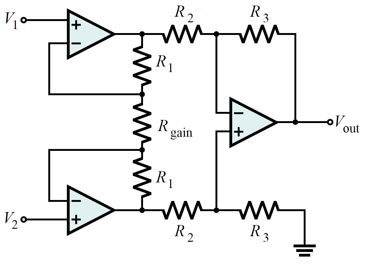
The main chip we'll be using in our amplifier circuit is an LT1167 instrumentation amplifier. An instrumentation amplifier is a special type of differential amplifier that includes an electrical buffer on each input to provide power when amplifying small signals. Without these buffers, the input voltage source (from the electrodes) would attempt to drive current through the R2 resistors on the inputs to the third op-amp, corrupting the signal. The diagram above shows the most common arrangement for an instrumentation amplifier.
With this basic understanding of how muscle activity can be recorded using a simple differential amplifier, let's build an amp!
Step 3: Circuit Diagrams
EMG Amplifier
For the EMG amplification, we'll follow the schematic for the "nerve impulse amplifier" described in the LT1167 instrumentation amplifier datasheet (shown below).

We'll assemble one of these nerve impulse amplifier circuits for each muscle we'd like to record from, which in our case is two. You only need to assemble one of these circuits if you're building a single channel amplifier. If you study the pictures of my assembled circuit in the next step closely, you'll notice a few extra resistors and capacitors than are shown in the schematics here. That's because I've added passive, first-order low-pass filters on the outputs of the instrumentation amps to further reduce noise. These filters aren't completely necessary but should help clean up your signal if you're interested.
Audio Amplifier
We'll also need to build a simple audio amplifier circuit to enable the output of the EMG amplifier to drive external speakers. We'll follow a circuit from the LM386 datasheet (shown below).

Keep these diagrams on hand as you're assembling the circuits. I don't know how many times I've fixed a problem with my circuit just by going back and making sure I've followed the diagram correctly. You'd think I'd know how to follow instructions by now...
Step 4: Power Supply
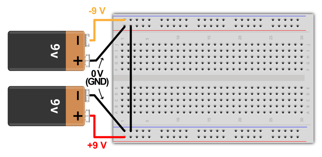
Before we can assemble our circuit, we need to prepare our power supply. If you look at the datasheet for the LT1167 instrumentation amp, you'll notice that it requires both a positive (+S) and negative (-S) power supply along with a ground. This need for a ±S arises from our desire to amplify muscle activity, which is inherently a bipolar signal. In other words, the electrical activity generated by muscles can either be positive or negative with respect to zero volts. The amplifier must therefore have both a negative and positive supply in order to accommodate and amplify these bipolar muscle signals. Without a negative supply, the amplifier would be unable to produce any outputs less than zero volts.
Two 9 volt batteries are both a convenient and safe way to power our EMG amplifier. Because we'll be attaching ourselves to the circuit, we don't want our circuit connected in any way to AC power from the wall. The diagram below illustrates how to connect the batteries in a ±9 volt arrangement.

Step 5: Prepare the Electrodes
As I mentioned above, we'll need a total of five electrodes for this project. EMG recordings are conducted with a differential amplifier, meaning we are amplifying the difference between two points of reference on the muscle. This means we'll need two electrodes per muscle. Additionally, we need a single reference for the muscle activity to be measured with respect to. Here is a link to some surface EMG electrodes sold on Amazon. The exact type of electrode isn't too important for our purposes. If you want to be extra fancy, you can attach solid-core wire to the ends of the electrodes like I've shown in the picture above to make them easier to plug into the breadboard.
I'll give more details for placing the electrodes after we've assembled the circuit.
Twisted wire pairs
You'll also want to twist the wires together for each electrode pair as shown above. The wire from the ground electrode does not need to be twisted to anything. In addition to cleaning up the mess around your circuit, twisted wire pairs help reduce electrical noise picked up by the electrodes. By alternating the position of the wires back and forth, any external electromagnetic interference (e.g. 60 Hz from mains) will affect the wires an equal amount. The differential amplifier will then remove this common noise signal.
Step 6: Assemble the Circuit
Follow the circuit diagrams shown in Step 3 to assemble the instrumentation and audio amplifier circuits. The final assembled circuit is shown below.

Step 7: Test It Out!
With the circuit assembled you'll be able to slap some electrodes on your arms and start listening to your muscle activity in real time. Like I've shown in the picture below, place two electrodes on the inside edge of each forearm, parallel to the length of the muscle and separated by about 2 cm. Place the reference electrode on the bony part of one of your elbows, away from the electrodes on the muscles. Of course, if you'd like to record from a different muscle, just place the electrode pair in the right position, taking care to align the electrodes parallel to the length of the muscle fibers.

Once the electrodes are in place and you've plugged into the speaker, power on the circuit with the two 9 volt batteries. Play around with the variable resistor to adjust the gain of the signal going into your speaker. You'll want to turn the gain up as much as you can until you notice clipping in the audio, after which you'll control volume via the speaker.
The audio in my video is clipping a bit, but it's a pretty decent example of what a clean EMG signal should sound like.
Step 8: Applications & Ideas
Building an EMG amplifier opens up a number of possibilities for interesting projects. As I mentioned in the intro, in addition to being a useful clinic tool, EMG recordings have become more common in basic science and engineering research as a control signal for various devices. Below are a few examples of EMG recordings being used in novel settings.
- Prosthetic limb
- Facial EMG for cursor control
- RC Car
- EMG for biofeedback
- Video game control
- MIDI controller
EMG recordings also play an important role in motor control research, a field of neuroscience devoted to studying how the nervous system initiates and coordinates movement. If you're interested in a more in depth look into that research, here are some cool papers from the field:
- Sequential activation of muscle synergies during locomotion (2006)
- The case for and against muscle synergies (2009)
- Computing Motion Dependent Afferent Activity During Cat Locomotion (2015)
I'd love to see what projects you come up with on your own! Let me know if you have any questions about this Instructable, I'd be happy to help.

Participated in the
Explore Science Contest 2017

Participated in the
Invention Challenge 2017

Participated in the
Power Supply Contest


