Introduction: Build the MFOs Sound Lab Mini Synth


So you want to build (or you already are building) Ray Wilson's Sound Lab Mini Synth? I did it; so can you! This instructable details my process and hopefully will provide some insights and helpful tips for your journey. I struggled with a few parts of the project because the documentation can get a little confusing. Hopefully you can avoid some of those struggles. This instructable will not tell you everything; consider this to be supplemental information to the documentation on the MFOs site.
Step 1: Populate Main Board


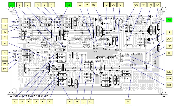
Populating the main board is relatively straightforward, but I would highly recommend checking each individual component and cleaning the leads with a green scouring pad to ensure functionality and proper connection. Work systematically, one component type at a time, from lowest profile on the board to highest. I started with resistors. I found that working numerically (R1, R2, R3, and so on) was tedious, so I populated in order of component value rather than number. Remember to double check everything before you clip off excess leads.
I worked with the full kit so I had all the components necessary for the build (minus case, panel, and the power supply I built).
I have conflicting advice on the placement of transistors and other heat sensitive parts. I went to the effort of heat syncing my diodes and transistors with heat sink clips. This is probably not entirely necessary. As a result, my transistors sit a bit higher on my board and are at risk of being bent. So, nothing is melted, but things could get messy down the line.
As you can see in the photos, I did not immediately place my ICs into the sockets. I waited until my power supply was fully tested and I was nearly ready to wire the board for the panel connections to place my chips. This is probably an unnecessary precaution but I thrive on worrying.
Step 2: Panel Design and Fabrication


I like cats. I could just leave this section at that because that really explains pretty much this whole process. Anyway, the story goes something like this... I am building my own synthesizer, it is mine, nobody else's, so I want cats on it. My electronic's mentor very grudgingly accepted this idea and wanted no part in it. But I did it! Here's how:
I spent a substantial amount of time making sure I was achieving the appropriate scale so that I would have enough space to populate the panel. There are few layouts on the MFOs site so I took one of them and brought it into photoshop to make a template for hole size.
The layouts that I had seen were not very intuitive, so I drew out my own. I really like the layout of the ARP 2600, it's really intuitive and flows well when doing live synthesis. I didn't have the space to work linearly, as I wanted a more compact design. I've included a diagram of the 2600 layout for reference.
My three oscillators (VCO1, VCO2, and LFO) are on the top row. The second row contains my VCF, Envelope Generator, and VCA. The bottom row contains my External Trigger, Sample and Hold, and Main Output Mixer. There is a separate panel for outputs and CV / Gate inputs.
Based on the relative size of the panel components (pots, switches, et cetera), I drew out some rough measurements for each section, and determined that I would need a piece of aluminum that was 11"x11". My panel design was 10.5"x10.5" so there would be a bit of allowance and room for screw holes on each corner to mount it on the case. I laid out my panel in PhotoShop and then drew a lot of cats in various positions (I did not end up using all the cats I drew). Then I came up with a lot of cat puns for the controls and labels.
I referenced the schematic and panel wiring documents to determine what components populated each section of the panel, and placed reference marks in my design for drilling. I then printed out my to scale design and drilled my panel. I then took my design to a friend with access to a printing studio and we burned a screen for silk screening, cleaned the aluminum thoroughly, then silk screened the panel with purple acrylic ink. This worked well but we couldn't do too many passes over the panel or the ink would likely smudge on the aluminum.
In hindsight, rather than silk screening the panel with acrylic ink, I should have etched it beforehand. I ended up using a few coats UV resistance clear acrylic coating to protect the design. All self criticism aside, the panel looks great and has held up well under use.
Step 3: Case Construction


To be perfectly honest, I am not entirely happy with my case. I used plywood to construct it and it was a flaky and splintery business. If you have the option, spend a little more to obtain good quality hardwood to construct your case.
I made my case large enough to contain my power supply, main board, add added modifications (sample and hold and external trigger boards). It was also made to fit my 11"x11" panel. It's not the most elegant case in the world, but it works.
I upholstered my case with glitter vinyl. This proved challenging as I had cutout sections for the output jack panel and power supply panel. Things went particularly awry when I stored the newly upholstered case in an electronics lab that was unbearably hot and poorly ventilated, as the vinyl then proceed to peel up and warp in places. Staples and metal amp corners helped a bit but I am fickle.
I am going to reupholster the case as soon as I get a chance because I am a perfectionist and I can't stand looking at it.
Step 4: Panel Population and Labeling


When I populated my panel I labeled each part so that wiring to the board would be easier. This was immensely helpful and made my life much better during the arduous process of connecting everything. Since I changed the layout of my panel and even moved some of the pots and switches around, labeling everything took a little legwork. I cross referenced the schematics with the panel wiring diagram.
I think labeling your panel components is well worth the effort and will save you effort in both construction and any future troubleshooting or repair work that may arise.
(As you can see there are two sections that aren't populated. Those will be the Sample and Hold and External trigger. I have to build those circuits).
Step 5: Panel Wiring


This is when things got crazy. Wiring the panel and board, as you can see, was a very intensive process. The board to panel wiring diagram was a helpful resource in tandem with the panel wiring diagram. Things got pretty messy for awhile, and I soon realized I need to group the wires. In hindsight, I would have made tape labels for each wire indicating the letter it corresponded to on the board/panel diagram. Labeling each individual wire would be useful for a number of reasons: it would streamline the wiring process and ensure proper connections, and it would be useful in easing future troubleshooting and repair work.
I measured out 2ft sections of a few colors of wire so that it would be easier to track down problems visually, and there would be no pull or strain on solders on either the board or the panel. I zip tied groups of wire together to keep everything neat inside the case.
On the panel, I used solid core wire so that I could bend wires neatly around components to prevent shorts and keep everything neat. Make sure the leads of panel components (namely the few diodes, resistors, and capacitor on the panels) are insulated to prevent shorting against the aluminum or other components.
Make sure your panel is also wired to ground! I'd suggest adding a lug somewhere on your panel that you can wire directly to your ground point. Since I built an alternative power supply to the battery supply implemented by MFOs, I wired directly to the ground point on my IEC jack.
Step 6: Optional: Regulated +/-9V Linear Power Supply


I thought that using two nine volt batteries was an absurd proposal for such a large piece of equipment (it works fine I am sure, but I am fickle), so I built a regulated +/- 9 V power supply. I will post a separate tutorial for this at a later date. If you are interested in how I did this, feel free to comment or message me and I'll hook you up with a schematic in the meantime.
Step 7: Testing and Troubleshooting

I would highly recommend keeping a digital multimeter and if possible an oscilloscope handy (to check signal from pins on chips). I continuity tested everything one million times (more like three) to make sure I had everything connected before turning on anything. I also tested my power supply thoroughly before hooking it up to the main board to make sure I was getting the correct voltages so I would not fry my board.
You know that old adage, "Measure twice, cut once"? That totally applies here. Just breath and calmly check every thing as systematically as possible. I worked through the schematic a couple times with both my multimeter and scope checking every single point. I had a ground hum (my panel wasn't properly grounded initially) and it turned out all the sound I was initially hearing was coming through some leak in the circuit. Once I got ground hooked up everything was dandy (besides my resonance pot on my VCF, which I think has a dead spot).
Something I've learned through troubleshooting a lot of circuits is that the problem is probably deceptively simple. Don't immediately jump to the worst case scenario (i.e: all my ICs are fried, or the whole thing is just plain broken). Take a step back, breath, check your schematic, and calmly proceed. If you try to troubleshoot some mysterious problem while you are frustrated and emotional, you are more likely to injure yourself and probably actually really break something.
Anyway, after all sorts of troubleshooting, my baby worked! Here it is in action (with a bonus conversation about Sci-Fi movies):
So there you have it! I built a synthesizer! Hopefully my trials and tribulations will help you in your build process! Good luck and godspeed.