

Introduction: Build Your Own Arduino - Bare Bone System


I’m going to provide the schematic for the system I am building here along with breadboard photos as it is constructed. You can also refer to the Standalone Arduino Tutorial on their website for breadboard photos and more explanations. (http://arduino.cc/en/Main/Standalone)
My Recommendation:
Before you attempt to make your own, buy one. Its much easier to troubleshoot this when you know how it works and whats going on. If you buy one or even just borrow one and have a chance to play with it, load some programs, test it all out, it will be a lot easier to troubleshoot what is wrong when you start building it.
Step 1: What's Needed

***NOTE*** : BOM stands for Bill Of Materials. This is simply a detailed list of each item that is needed, the quantity, price, etc to catalog all the necessary information.
Components (included in BOM):
1. 1 x LM1117T-3.3/NOPB Voltage Regulator (3.3V)
2. 1 x LM7805CT Voltage Regulator (5V)
3. 1 x LED RED
4. 1 x LED GREEN
5. 2 x 220 Ohm resistor
6. 1 x 10k Ohm resistor
7. 4 x 10 uF capacitor
8. 2 x 22 pF capacitor
9. 1 x 16 MHz clock crystal
10. 1 x Atmel ATmega328P-PU AVR microcontroller WITH ARDUINO BOOTLOADER
11. 1 x 28 Contact DIP Socket
12. 1 x 9 Volt Battery Connector
13. 1 x 9 Volt Battery
Also needed (not included in BOM):
14. 22 AWG wire
15. 5 Pin Header
16. 1 x small momentary normally open ("off") button
17. 1 x FTDI FT232 USB Breakout board
18. Breadboard (prototyping board)
Step 2: The Components

LM1117T-3.3/NOPB Voltage Regulator (3.3V)
This component is a voltage regulator that converts 5 Volts into 3.3 Volts. This voltage regulator is not required. I’m placing it into my system for components that may require 3.3 Volts power later down the road. You can choose if you need it or not based on your requirements. If you are not using this you can also remove two of the 10 uF capacitors from the BOM.
LM7805CT Voltage Regulator (5V)
This component is a voltage regulator that will convert 10 Volts (or out 9 Volt power) to 5 Volts. This will power any components that require 5 Volts power along with our entire board. This Regulator is necessary for this tutorial. The CT on the product id is not important, just that it is an LM7805 Voltage Regulator.
LED RED
This will be an indication LED for power. You can choose any standard LED you would like, aim to have the forward operating voltage around 2.2 Volts, but it will really work as long as it is under 5 Volts.
LED GREEN
This will be another indication LED. You can choose any standard LED you would like, aim to have the forward operating voltage around 2.2 Volts, but it will really work as long as it is under 5 Volts.
220 Ohm resistor
These will be used to limit the current to the LED’s. Not much to explain. Just get ¼ Watt 220 Ohm Resistors.
10k Ohm resistor
This resistor will be used for the reset button. Not much to explain here either. Just get a ¼ Watt 10 kOhm Resistor
10 uF capacitor
These capacitors are going to be used in the power section of our board. They are used to condition the input and output power to each of the Voltage Regulators. The system would probably still work without them, but it is highly recommended you used them. Just need any 10 uF electrolytic capacitor that is rated for 10 Volts or higher. If you are NOT using the 3.3 Voltage Regulator you only need to purchase 2 of these. (2 for each Voltage Regulator)
22 pF capacitor
These are used for the timing system. They are required for it to operate correctly. You should get two ceramic 22 pF capacitors.
16 MHz clock crystal
This is the main component to the timing system. It is required for the processor to operate correctly with the Arduino programmer. You can purchase any standard 16 Mhz clock crystal with two pins.
Atmel ATmega328P-PU AVR microcontroller WITH ARDUINO BOOTLOADER
This is the main part to our system, the microcontroller. The ATmega328 is the same chip used in the Arduino UNO. In the BOM I have added the ATmega328P-PU with Arduino Bootloader Pre-loaded. This means you will be able to wire it up and program it with the Arduino software without needing any extra special equipment. If you would like, you can purchase a blank ATmega328P-PU, but you will then need to use an ISP programmer to load the Arduino Bootloader. I will cover this more later.
28 Contact DIP Socket
This is simply a holder for the ATmega328 chip. It is only really necessary if you plan on soldering the chip onto a board. If you plan to use the chip on a breadboard only where soldering will not be done, then you do not need this part.
9 Volt Battery Connector
Any type of 9 Volt battery connector will work. I have chosen a simple connector with wire leads in the BOM.
9 Volt Battery
Any 9 Volt battery will work. I chose mine based off price at the purchase time.
22 AWG wire
This was excluded from the BOM because I had some already. Any type of testing or prototyping wire should work. You can either purchase it online with your order or at a local hobby shop if you don’t have any around
5 Pin Headers
This is needed to connect the FTDI breakout board. We will be setting up our board so there will be 5 pins sticking out of the board where we can make the connection and quickly program. Any form of header pins or wires that will make the connection will work. Just pick something easy for you.
Small momentary normally open ("off") button
This was excluded from the BOM because I had a bunch lying around. You can really choose any switch you would like as long as it is a MOMENTARY switch that is NORMALLY OPEN or OFF. You can see the one I chose in the photos later.
FTDI FT232 USB Breakout board
You will need an FTDI Connector to program the Arduino. I recommend just purchasing it from Sparkfun.com. They have quality equipment for not so bad prices. Search FTDI on their website and just make sure you purchase the 5 Volt version.
Breadboard (prototyping board)
Any standard breakout board or prototyping board you would like to use works. Just something for us to test and troubleshoot on.
Again, you can choose to adjust or leave out any materials you’d like, but if you don’t know exactly what you are doing, I would recommend just purchasing the exact BOM. When I made this purchase the total cost for all my parts was only $10, so it isn’t bad to just make the same purchase.
Step 3: Getting the Components
The next item is a CSV file for Newark.com. If you are happy with the list of items I chose, you can go to Newark.com and simply upload the CSV file to instantly have all the parts added to your cart.
Remember you can make any adjustments to the components you would like, but for reference, these are the components I am using in my tutorial.
You can also purchase the parts from any manufacturer you’d like. I like using Newark Element 14, and I was able to find all the components I needed on their site, but feel free to put together your own cart with any other manufacturer. The items marked as 0 in the quantity column are items that you need but I already had, so I didn’t purchase it.
Also keep in mind the prices of the parts make change over time. You can see in the Notes section which parts were on sale when I purchased them. The prices should stay relatively the same, but don’t be alarmed if my prices on the BOM are different than the ones you are finding.


Step 4: Schematic


This schematic contains all of the parts listed above. Some of them are abbreviated or symbolized differently, just look at the values and names on them to determine which part is which. If you are using a breadboard you can use this schematic as reference for each pin connection.
I would recommend opening the image in another tab of your browser so you can refer to it easily
Also, i have attached a pin mapping illustration for both the Atmega328 pins and their corresponding Arduino pins. Be careful while wiring to which pins are being referred to. Most of the time I will be referring to the Atmega328 Pin numbers.
EDIT: I've added the eagle schematic here
Attachments
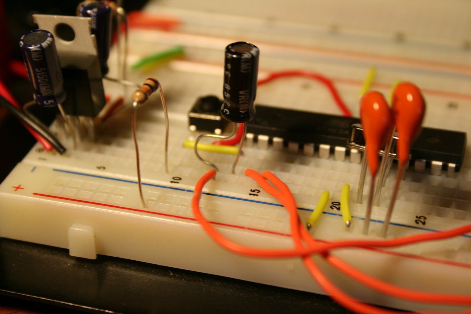
Step 5: Assembling the Board - Part 1 - Power


The first part to assembling the board will be the power section.
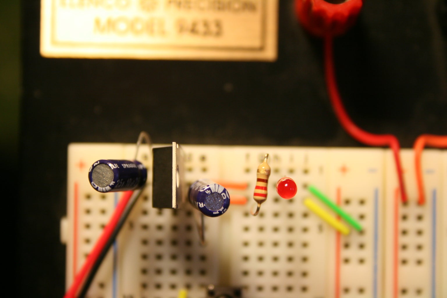
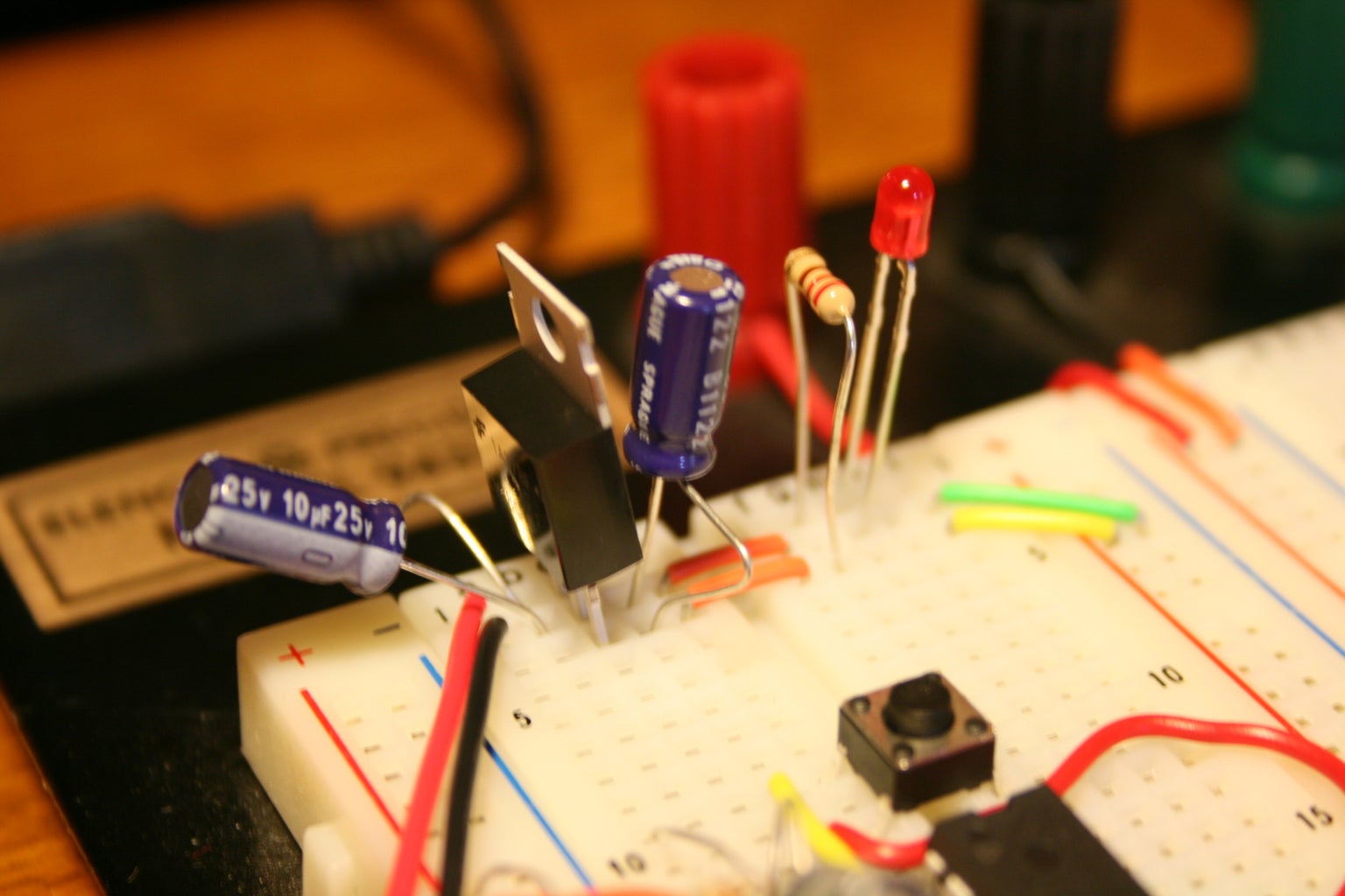
Take your LM7805 Voltage Regulator and place it somewhere at the top of your bread board similar to how it’s shown in the photo. When the regulator is facing you, the left pin is the input, the right pin is the output, and the center pin is the ground. Connect your 9 Volt battery connector to the input and ground. Then place a 10 uF capacitor between the input and ground and another between the output and ground.
Next place a 220 Ohm resistor plus the Red LED between the output and ground of the regulator. This is our power indication LED. Make sure the pin where the resistor and LED are connected is separate from any other pins we’ve used so far. The Resistor LED should be one path from the 5 volt output to ground and the short pin of the LED should be going to ground. Next you can connect the 5 volt output and ground to the rails on your breadboard. This will allow us to tap into the power and ground from the entire length of the breadboard.
That’s it for the 5 Volt power. For the 3.3 Volt power (if you chose to use it) simply follow the same guidelines as for the 5 volt power except for the following: It isn't shown on the schematics, but follows the same format, so you should be able to replicate it easily. THE PINS ARE DIFFERENT. Please review the datasheet for the pinout. The input to the 3.3 Volt Regulator will be the output of the 5 Volt regulator, you do not need an indication LED unless you would like one, and do not attach the output of the 3.3 volt regulator to the same rails the 5 volt regulator is attached to. I would just leave it in a small section on the other side of the breadboard for tapping into when needed.
Step 6: Assembling the Board - Part 2 - the Chip


We will now be placing the main chip on the board.
Check out the photos.
Place the chip over one of the channels on the board so that the pins are not short-circuited with the other side’s pins.
Now set up the power to the chip. Please note these are the ATmega328 Pin numbers, they do not correspond directly to the Arduino Pins. Refer to the illustration for the Atmega328 Pin-out labeling. There are two places where you need to connect both power and ground, and if you set up the rails on both sides of your breadboard this will be very easy. You will need to connect power to pins 7 and 20 and ground to pins 8 and 22.
That’s it for powering the actual chip. Before turning on the power, make sure these connections are correct. If you switch them by accident you will burn the chip out and need to buy a new one.
Step 7: Assembling the Board - Part 3 - the Clock


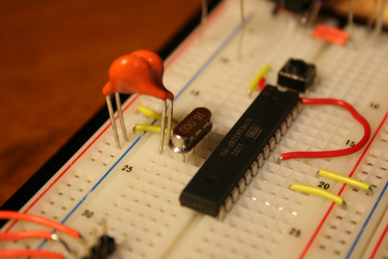

We will now set up the Clock Crystal for the chip. This can look a little complicated, but it’s easier than it looks.
The pins for the crystal are pins 9 and 10.
First connect the crystal between these two pins.
Then take the 22 pF ceramic capacitors and connect one from each pin to ground. The easiest way to do this is to simply connect from the channel the pin is on, to the ground rail along the side. Take a look at the photos to see how I did this.
That’s it for the clock, if your timing seems to be off when running programs come back to this and make sure you connected it correctly and used the correct capacitors.
Step 8: Assembling the Board - Part 4 - the Reset Button


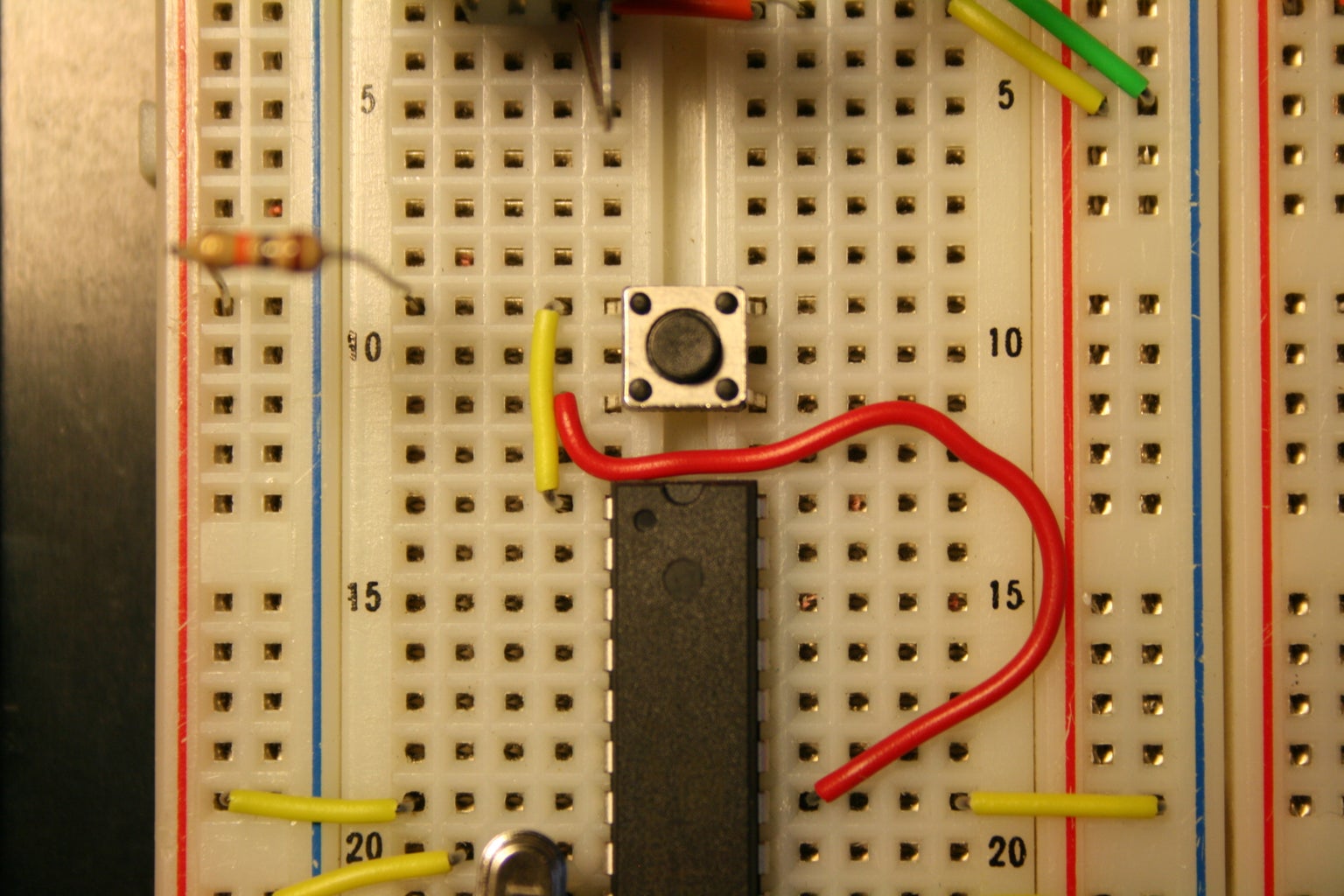
This will be the reset button for resetting the program on your board.
Place the switch (mine has 4 pins) across the same channel your chip is over top of. Connect a resistor between the 5 volt power and the top left pin of your switch. Then connect the same top left pin of your switch to pin 1 of your chip (the reset pin). Then connect the bottom left pin of the switch to ground.
This setup will allow you to reset your program by momentarily pressing the button. If your program doesn’t seem to be starting up, this may be one spot to check.
Step 9: Assembling the Board - Part 5 - the FTDI Header

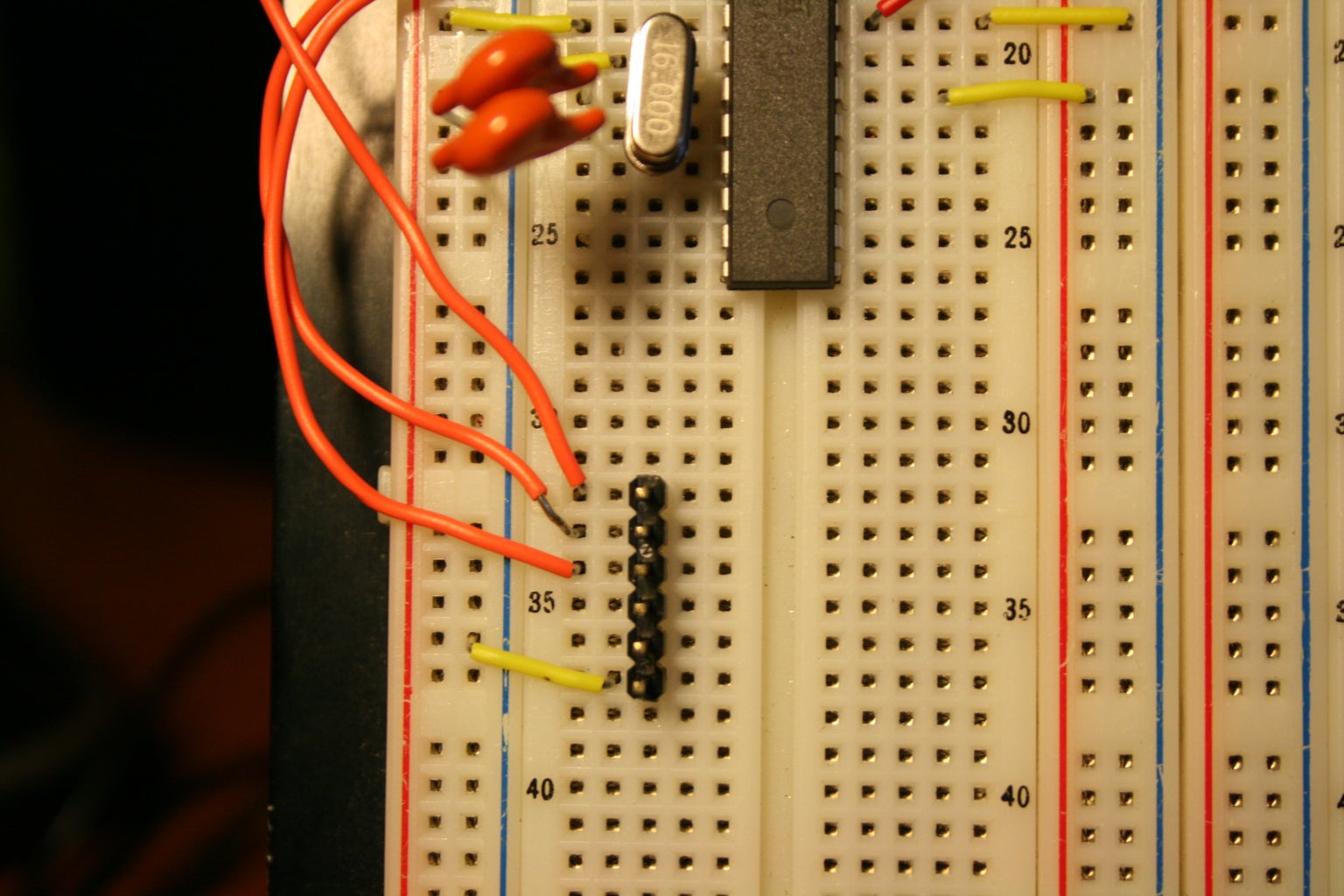


This will be the place for us to connect the FTDI Breakout Board to program out board.
We will need to make 4 connections. Pick about 6 rows on your breadboard where you can place headers or wires to connect.
The first connection we will call row 1. This will be the top row. You can refer to the schematic or photos to get a better idea of this. Connect row 1 to ground. We will then skip the next two rows. Connect row 4 (TX) to the ATmega328’s pin 2. Connect row 5 (RX) to the ATmega328’s pin 3. Connect row 5 (DTR) through a 1 uF electrolytic capacitor to the ATmega328’s pin 1 (reset pin we dealt with earlier).
Two main things to know here. First, we are not connecting the power pin. We are not doing this because the board will be powered by the battery at all times and we don’t have a safety system set up to prevent short circuiting the battery and computer power. This means that you will always have your battery connected, even while programming it needs to be connected. If you would like to use the computer to power, simply remove the battery and connect the power (row 3) to the power rails on your board. Second, the DTR pin. This pin connection through the capacitor allows the program to automatically reset the chip while programming it. If you don’t have this connection made your chip will not program and you will get an error message. Alternatively you can press the reset button on your board when programming, but this connection is just easier.
And that’s it for setting up the board, we can now move on to programming the first program.
**NOTE1** - I apologize for not including a picture of the FTDI board connected to the header pins. you should be able to tell from the wiring which is ground, etc, and line them up correctly with the FTDI board, but for help i will explain that when viewing image #2, the first picture of the board here, the FTDI board's top face (with the chip and LEDs on) would be facing to the right.
**NOTE2** - I have corrected the mistake in the schematic and in the description with the FTDI RX and TX pins being swapped.
Step 10: Programming It

We are going to use the free Arduino software to program our board (because we already have a chip with the Arduino bootloader on it).
Go to their website Arduino.cc and download the latest software.
When you open the software, select the Tools menu. Under the “Board” option, select “Arduino UNO”. You will also need to make sure the “Port” connection is correct. If you can’t tell what’s going on with it, try reading on the Arduino.cc website about troubleshooting.
For testing reasons let's use the sample program Blinking LED to test our board. We will need to take another resistor and LED and connect it from Arduino pin 13 to ground (put the short end of the diode to ground).
Load the program by going to File>>Examples>>1.Basics>>Blink, or by downloading it here and opening it. It should look identical to the first image.
Hook up the FTDI connection and hit upload and see what happens. Remember that either only your battery connection should be made and not the FTDI power connection, or vice versa. If you followed everything correctly and made the connections correctly, everything should work well. Some lights will flash and once the software has finished uploading the LED should start blinking on and off.
If you get an error message, double check all of your connections. If you don’t see any lights flashing check which port you have selected in the software and make sure the FTDI plug is connected correctly.
If all has gone well and you see the LED flashing on and off then this tutorial is complete.
If not, well sorry but this is where it gets tedious. You need to troubleshoot each connection. Check each one, check each component is correct, try searching your issues on Google to see if anyone else has had the same issue. I can give advice through messages and comments, but there is only so much I can do without the circuit in front of me for messing with.
Step 11: OPTIONAL – Programming Bootloader With ISP Programmer

I've posted another instructable covering just the ISP programmer. Check it out HERE if you're interested in using this technique.
Pros: No bootloader, which means faster startup/reset times
More space on chip available to use (the space the bootloader used to use)
Cons: A little more work
More equipment needed
