

Introduction: CNC Reindeer Decoration (Hangable)

Presenting the CNC Reindeer Decoration, a project by Joseph Adigwe, a student at Pan-Atlantic University, Lagos, Nigeria. This project aims to offer a simple and enjoyable way to beautify homes and offices. You can easily create this decoration from the comfort of your home or workstation. It's a great opportunity to enhance your design, art, CAD, and CAM skills all at once. Plus, you'll have a unique decoration to impress your friends or colleagues when they visit!
Supplies

Fusion 360 software
A reference image of a reindeer
A CNC Machine
Wooden material of your choice
White paint (optional)
Attachments

Step 1: Download and Insert Reference Image
The reference image is attached in the supplies section. Once you download it, you can insert it into your fusion 360 workspace as a canvas.
Step 2: Adjust Reference Image to Match Preference

After inserting the image into your workspace, you can arrange it on a plane of choice (I used the x-y plane) and scale it to whatever size you wish it to be (the size of my decoration was about 500mm by 500mm so I scaled the image to be a little over that).
Step 3: Create a 3d Flat Base for the Design

This step can quickly be done using the BOX command from the CREATE dropdown. The box should be about the size of the actual reindeer head in the image.
If you wish to, you could actually create the box base before inserting the reference image so that you can fit your reference image to match the base instead. Anyway is fine though.
Step 4: Create a Sketch of the Outline of the Image


For the step, I made use of the LINE tool, the intention is to create a closed geometry so that it can be extruded later. This can be done by tracing out one half and then mirroring it over to the other side (using the appropriate axis line {y-axis in my case} as the mirror line or creating a line in the middle that can be used as the mirror line then deleting it after if you wish) since the reference image is symmetrical.
Step 5: Create Another Sketch of the Holes in the Reindeer Head


When creating the sketch for the holes, similar to the last step (because the image is symmetrical) you can decide to sketch one half and mirror it to the other half. To make the mirroring easier however, I did not do it in the sketch but instead when I was extruding. This was done by using the MIRROR command from the CREATE dropdown in the SOLID tab. When you select the mirror command, you should change the object type from bodies or faces to features (this will be expanded on in a future step).
There's a bit of freedom here as the holes created do not have to match the reference image exactly and can be tailored to fit your preferences. In my model, I decided to leave some holes out as I felt it made it look better and a little more simple.
When creating your holes, ensure that all holes are closed geometries by make using of a coincident constraint between the first and last line of each hole (if that has not already been done automatically for you).
You can also create outlines around the eye which will be extruded later.
Step 6: Select the Closed Geometry Between the Holes (and the Two Eyes) and Extrude Them


The height you will extrude too will be dependent on the piece of material you have and on the capabilities of your CNC machine.
You can use the parametrictimeline to go back to past features and make any necessary edits if you feel the extrusion does not give desired results.
When extruding, you can change the operation from NEW BODY to JOIN since the intention is to use one piece of wood.
In my own version, I extruded my outline sketch using the operation JOIN and then made another extrusion of the holes sketch using the operation CUT. You can choose to do that instead if you prefer to.
After the CUT extrusion, I then used the MIRROR command as explained in the previous step to mirror over the hole cut extrusions from right to left. For me to be able to select the extrusion cut feature from the parametric timeline, I had to first set the object type from bodies to features after which I could then select. The mirror plane used was the y-z plane.
Step 7: Creating Set Up for the Machining Process


After the model was completed in the DESIGN workspace, I moved over to the MANUFACTURE workspace to set up for the machining process.
For the setup, the machine type can be set to whatever CNC machine you have available. Unfortunately, I do not have a CNC machine readily available.
Note that the processes carried out in this set up may have to be altered to fit your own CNC machine and so you may not have to strictly follow the steps related to set up.
However for the setup:
I set the operation type to MILLING;
I selected the bottom left corner as the stock point;
I selected the CNC Reindeer head model as the model;
I set the stock mode to RELATIVE SIZE BOX;
I set the STOCK SIDE OFFSET and STOCK TOP OFFSET to 1mm (If it is already set to that, you can skip this).
Step 8: Getting Tool Paths


For the machining process, I made use of three operations: 2D Face, 3D Adaptive clearing, and then 2D Adaptive clearing. I will put you through the set up for each of the operations.
2D Face
For this operation, I used a 10mm diameter flat end mill tool and selected the top part of the relative size box as the geometry. I then clicked on OK and the toolpath was automatically generated.
3D Adaptive Clearing
For this operation, I used a 10mm diameter flat end mill tool and under the geometry section, I selected the machine boundary selection as the point between the outline of the base and the outline of the Reindeer model. I then clicked on OK and the toolpath was automatically generated.
2D Adaptive Clearing
For this operation, I used a 4mm diameter flat end mill tool and under the geometry section, I selected the pocket selection as all the holes made in the Reindeer model. I then clicked on OK and the toolpath was automatically generated.
For each of the operations, I simulated after setting up to ensure the result was as desired. For the simulation, I set the toolpath mode to TAIL and the stock material to PLASTIC VINYL.
Step 9: Simulating Fully With Machine


In this step, you will simulate all the operations together after setting up your CNC machine specifications. Unfortunately, I do not have much images for this step because I do not have access to a CNC machine. After simulating, you can export the G-code in post-process and proceed with your machine.
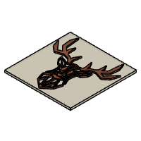
Once you have completed the process, your finished work should look like the images attached. You can paint the background of the reindeer white or make any other little design changes you would like to make it fit your style. I have attached the f3d file for reference.
Hopefully it goes smoothly and I wish you the very best!
Attachments

Participated in the
CNC Student Design Challenge


