Introduction: Chicken Theremin
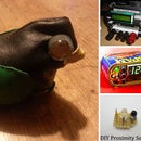
We made this chicken as part of the Instructables August Build night with Jameco. Our makerspace is called Make Shop, we're in Dublin and we're part of the Science Gallery. Since Jameco were nice enough to give us some 555 timers, we thought it would be cool to use them to make some crazy noises. We had some LDRs in the shop so we used the breadboards to prototype a small light sensitive synthesizer circuit. I later transferred it onto a tinier breadboard, and then onto stripboard. Then I put it in a chicken because I thought it would be funny. When you're making this yourself, you can use anything you want! I replaced the chicken's eyes with the LDRs, but you could use a bear, a cat, a weasel, a handbag, a hollowed-out book, a sombrero, an Altoids tin. It's up to you and your imagination.
Step 1: Things You Will Need
555 timer chip
IC holder
2x LDRs
1M resistor
10k resistor
4.7uF capacitor
0.22mF capacitor
8 ohm 0.5W speaker
Coin cell battery holder
2x CR2016 3V batteries
Tiny stripboard
Assorted lengths of wire
A chicken or something
Again, we were given some of these components by the nice people at Jameco!
IC holder
2x LDRs
1M resistor
10k resistor
4.7uF capacitor
0.22mF capacitor
8 ohm 0.5W speaker
Coin cell battery holder
2x CR2016 3V batteries
Tiny stripboard
Assorted lengths of wire
A chicken or something
Again, we were given some of these components by the nice people at Jameco!
Step 2: Solder on the IC Holder, Resistors, and Jumper Wires
Place the IC holder in the centre of the little stripboard, and tape it on to keep it from falling off when you flip the board over. Flip it, and solder all 8 of the pins. Your little helping hands man will help you here. Then, add the resistors. The 1M resistor needs to go from pin 1 to pin 2 on the IC, and the 10k one goes from pin 7 to pin 8. Now we need to connect pin 2 to pin 6 with a jumper wire, and pin 4 to pin 8. Solder these on.
Step 3: Solder the Capacitors and the Speaker
The 0.22uF capacitor goes between pins 1 and 2 of the chip. The negative leg of the 4.7uF electrolytic capacitor goes at pin 3 of the chip, and the positive leg goes to a point on the right. Next we need to attach the speaker. It has a positive and a negative pole but it doesn't matter which is which. One wire goes beside the positive leg of the 4.7uF capacitor and gets soldered on, and the other wire gets soldered onto pin 1 of the chip.
Step 4: Attach the Battery Holder
I have attached some wires to the pins to make it more accessible from inside the chicken. The positive leg goes to pin 8 and the negative leg goes to pin 1.
Step 5: Attach Your LDRs and 555 Timer
So I have poked holes in the chicken's face and attached the two LDRs to his eyes. You can't see too well in this photo but the chicken is at the end of those wires. So at this point, attach your LDRs to the outside of your thing. I have attached these in parallel, you could attach them in series either. Depends on the kind of sound you want. One leg from each LDR goes at pin 3, and the other legs go at pin 6. Solder away. Now insert the 555 timer and you're done! Here's a video to show the kind of mad sounds the chicken can make.


