Introduction: Communication Board (Aided AAC Device)
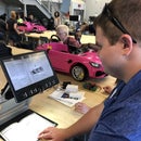
The goal of this project was to create an Augmentative and Alternative Communication (AAC) device for a child named Ethan who has Cerebral Palsy and Epilepsy and is nonverbal. The objective of this board is to allow him to better communicate with those around him and express his wants and needs.
Step 1: Introduction
This board is an evolution of his pre-existing AAC device which is a passive paper board that provides no tactile or auditory feedback. Working with his speech therapist at school as well as his parents it was decided that this board should provide auditory feedback in the form of pre-recorded sounds that match the words on his board. It was also requested that the board provide tactile feedback in the form of a click when each button was pressed so that Ethan knew he had pressed the button. This board was created over the span of 12 weeks and was created with the help of Ethan's speech therapist and and parents.
Step 2: Research
Research on AAC Devices
Before discussing the build, I will discuss some research behind the effectiveness of AAC Boards and how research on these devices drove decisions that were made in the design process. Augmentative and Alternative Communication or AAC is an umbrella term for any communication that is outside of general speech and has two categories, aided and unaided. Unaided AAC is anything from facial expressions, to writing, and sign language. The device I am making for Ethan falls under the category of aided AAC which includes communication boards, speech generating devices, and tablets.
For children like Ethan who have Cerebral Palsy, speech impairment is very common, and it is estimated that over 50% of children with CP have some type of speech impediment(Nordberg), with an estimated 32% of these children being completely nonverbal(Darling-White). This large population of children who have speech impediments demonstrates the need for aided AAC devices to allow them to communicate more effectively and to act as a learning tool to help aid in speech development.
AAC devices provide children and adults who have speech impediments or communication difficulties a way to converse with the outside world. It allows them to share their wants and needs without those around them having to guess. These devices have also been proven to improve the speech and language skills. According to a study done on users of AAC devices “89% of participants who are AAC users improved their speech skills” (Cakmak). In the case of Ethan, our hope is that the use of this device will help him communicate with us on a daily basis and will eventually lead to the development of new spoken words for him.
References
Cakmak, Kevser. “What Are the Benefits of Using High-Tech AAC?” Otsimo, 12 May 2017, https://otsimo.com/en/benefits-using-high-tech-aac/#:~:text=AAC%20communication%20can%20be%20beneficial,%2C%20school%2C%20and%20general%20life.
Darling-White, Meghan, et al. “Characteristics of Speech Rate in Children With Cerebral Palsy: A Longitudinal Study.” Journal of Speech, Language, and Hearing Research, vol. 61, no. 10, Oct. 2018, pp. 2502–2515.
Jansheski, Gina. “Cerebral Palsy and Augmentative and Alternative Communication (AAC).” Cerebral Palsy Guidance, 19 Apr. 2020, https://www.cerebralpalsyguidance.com/cerebral-palsy/living/augmentative-and-alternative-communication/.
Mei, Cristina, et al. “Motor Speech Impairment, Activity, and Participation in Children with Cerebral Palsy.” International Journal of Speech-Language Pathology, vol. 16, no. 4, 2014, pp. 427–435., https://doi.org/10.3109/17549507.2014.917439.
Step 3: Supplies and Tools Used
Buttons
- White 3D Printing Filament
- Oracal 651 Permanent Vinyl
- Black
- Blue
- Red
- White
- 1" Upholstery Foam
Electronics
- 2x Mini PCB Solderable Breadboard
- Large Solderable Breadboard
- On/Off Rocker Switch
- Panel Mounted USB Extension
- 24AWG Stranded Silicone Wire
- Li-Ion 3.7V 2600mah Battery
- JST-PH Battery Connector
- Adafruit FX Sound Board
- Adafruit Audio Amplifier
- Adafruit Battery Backpack
- 2x Tactile Switch Buttons
- 40mm 3Ohm 3 Watt Speaker
Hardware and Misc
- Assorted M3 Hardware
- BSI Thin and Medium CA Glue
- 1/4" x2'x4' Birch Plywood
- Black Spray Paint
- Spray on Clear Coat
Tools Used
- Laser Cutter
- Cricut Vinyl Cutter
- Hand Wood Clamps
- Soldering Iron
- Misc. Hand Tools
Step 4: CAD Design and Files
Design Requirements
This build had three major design requirements:
- It must be compact enough to fit in a backpack
- It must be safe for Ethan to use.
- He tends to slap things relatively hard when indicating what he wants
- It must include most symbols from previous AAC board
- It cannot be "flashy"
- Ethan has used an Ipad as an AAC device before but it was not successful because it was too distracting as a "toy"
CAD Design
After determining the requirements for the AAC device, a full CAD or Computer Aided Design of the AAC board was created in order to ensure correct dimensioning of all parts and to provide files for laser cutting and 3d printing. This CAD design was created in Autodesk Inventor and was tested digitally to give the best chance of proper fit when making the physical parts.
Things I took into account when creating the CAD design were mounting hole size and spacing for the breadboards and buttons, tolerances between the buttons and frame, mounting hole and access hole for the USB charging lead, and mounting hole size for the on off switch.
In order to view the full CAD design in inventor, download all .ipt and .iam files into one location. Then open the file "AAC Full V3".
BUILDERS NOTES - If you are creating your own CAD design to laser cut ensure that you measure the exact thickness of the wood you will be using as listed wood dimensions are not always accurate. For example the .25" birch used is actually .18". Also make sure to test a single 3d printed button mechanism thoroughly before printing the full set to ensure that the button travels the correct amount and presses the switch from all button locations. I found that my original button design had a few dead zones that would not press the electronic switch to activate the sound. This was unacceptable because it would impede on Ethan's ability to connect the press of a button to the auditory feedback that the board is supposed to provide.
Attachments
Step 5: 3D Printing and STL Files
Print Testing
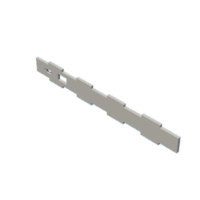
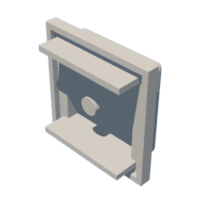
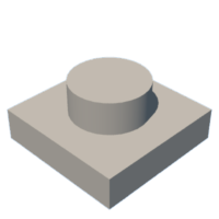
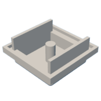
First upload one "Button Cap V3" and one "Button Base V2" file into the 3D slice of choice and ensure that scaling is correct. The overall size of the Button Cap V3 part in the slicer should be ~63.5x63.5x29.1mm. If this is not correct, scale the file appropriately. In my case I needed to scale the file by 10x or change scaling from 100% to 1000% after importing.
Next Print ONE of each of the files to ensure proper print settings. Also assemble this single set of parts to ensure that the parts work properly before printing the full set of buttons. This will prevent you from wasting filament, I made this mistake and wasted half a roll of filament because the first batch of buttons needed design modifications that I did not discover until after assembly and I had to re print all of the buttons.
Once you are happy with the buttons print 11x of each of the button parts.
Note, In order to get a smooth top surface for each button, I printed the button caps upside down directly on the print bed. The only bed adhesion I used was skirt. This causes a very smooth surface for the button caps that does not require sanding.
Print Settings I used
- Layer Height - .2mm
- Initial Layer Height - .2mm
- Wall Thickness 1.2mm
- Top/Bottom Thickness - .8mm
- Infill - 25%
- Support - Everywhere
- Support Overhang Angle - 45
Print temperatures, speeds, and bed adhesion should be tuned to your printer.
Step 6: Laser Cutting Plywood Frame
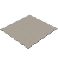
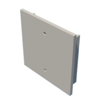
I used an Epilog Fusion 40 Laser Cutter to cut the outer frame of the AAC Device. This ensures that the plywood pieces are cut precisely and will help with assembly. In order to upload the inventor parts to my laser cutter, I exported the parts as a pdf file which is attached to this step. If you do not have a Laser cutter, these parts could be cut by hand using the full size PDF as a template for cutting. If using a Laser cutter, upload the files and cut according to your lasers requirements.
The .ipt parts that need to be cut are:
- 1x AAC Box Bottom V
- 2x AAC Box Side RL v2
- 1x AAC Box Side TB v2
- 1x AAC Box Top V2
- 1x AAC Box Top v3
Cut these pieces out of the 1/4" birch plywood.
Attachments
Step 7: Painting
Once the plywood pieces are cut, paint one side of them using whatever color spray paint you would like the frame of the AAC device to be. I chose black and used Rust-oleum 2x Ultracover satin black spray paint. I used 3 coats of paint on the plywood pieces to get a good finish with solid color. Allow the pieces to fully dry before continuing.
Step 8: Button Breadboard Prep
The next step is to solder the Tactile Switch Buttons onto the Mini PCB Solderable Breadboards. Follow the steps below:
Button Placement
- Take one breadboard and one button.
- Place the button onto the top of the breadboard, with the buttons pins going thorough G8, G10, D8 and D10 on the breadboard.
- Flip the board over and solder the pins to the bottom of the breadboard, securing it in place.
- Repeat these steps for 11 breadboards and buttons.
Wire Preparation and Soldering
- Cut 4 15' lengths of green 24awg wire , 4 8" lengths of blue wire and 3 4" lengths of white wire.
- Also cut 4 7" and 4 3" lengths of black wire.
- Solder one green of the cut wires onto breadboard location H10 for 4 of the boards that were prepared with buttons.
- Repeat this soldering step with the the 4 blue wires and the 3 white wires.
- Next solder 1 of the 7" lengths onto the C8 location of the breadboards that have the green wire, repeat with the other 3 green wire breadboards and 7" lengths of wire.
- Next solder 1 of the 3" lengths onto the C8 location of the breadboards that have the blue wire, repeat with the other 3 blue wire breadboards and 3" lengths of wire.
- Finally solder a 6" length onto location C8 of the breadboards that have the white wire.
Initial Button Prep
Finally install each bread board that was just prepared onto a "Button Base" that was 3d printed. The holes in the corner of the bread board should align with the 4 tiny pegs on the button bases.
Step 9: Initial Assembly
Next Install all 11 of the prepared button bases and breadboards onto the laser cut piece "AAC Box Bottom V" using 3mm bolts and nuts. Each button assembly should align with holes that were cut in the box bottom to allow 2 3mm screws to secure the assembly to the base.
Step 10: Main Breadboard Wiring
The next step is to solder together the main soundboard components onto the main breadboard. Follow the steps below and reference the wiring diagrams provided.
Attaching Battery Backpack
- First flip the backpack over and solder together the 500mAh jumper on the bottom to allow for faster charging.
- Next solder two long 24awg wires to the pads that are directly next to the battery connector after cutting the ribbon between them. This is where an on off switch will be attached in later assembly.
- Using the extra long provided pins for the battery backpack, solder it to the top of the soundboard, connecting the Bat, G, and 5v pins on the backpack to the Vin, G, and Bus ports on the soundboard respectively.
Attaching the Amplifier to the Breadboard
- Using the pins provided with the amplifier, solder the amplifier to a new breadboard, aligning the amplifiers A+, A-, SD, Vin, and Gnd pins to E24, E25, E26, E27 E28 respectively.
Attaching the Soundboard to the breadboard
- Next solder the soundboard onto the main breadboard aligning Batt and RST on the soundboard to I6 and C6 on the breadboard respectively. Use the provided pins to solder these two components together.
Jumpers - All done with 24 awg wire
- Connect J17 to C 24 on the breadboard. This will connect pin R on the soundbaord to pin A+ on the amplifier.
- Connect B25 to ground, grounding row 25 A through E. This grounds the speaker.
- Connect B27 to the power line, providing power to Row 27 A through E. This provides power to the amplifier.
- Connect A28 to the ground line, grounding row 28 A through E. This grounds the amplifier.
- Connect B19 to the ground line, grounding row 19 A through E. This grounds the sound board.
Step 11: Electronics Mounting
Next mount the main breadboard holding the soundboard to the top of the box base that is holding the previously mounted switches. Mount this by drilling two 3mm holes for the mounting holes on the breadboard. Then use two m3 bolts and nuts to mount this main board. Next connect the speaker to the amplifier speaker outlet port using a small screwdriver to tighten the connector down onto the speaker wires. Do not connect the battery yet.
Step 12: Wiring Buttons to Main Breadboard
Next follow the wiring diagram to connect the buttons to the main breadboard. A summary of the wiring is below.
- The ground wire for the bottom two rows of buttons will be run to the top most button in the row in parallel.
- The ground for the top most button will be run to the ground line on the main breadboard.
- Each colored signal wire will be run to a separate activation pin on the soundboard. These wires will go to A1-17.
- Note, run the signal wires in order from to to bottom and left to right, with the top left button going to A1 and the bottom right going to A17. This will help when adding sounds to the breadboard.
Step 13: Soundboard Sounds and Testing
The next step is uploading sounds to the soundboard and testing the electronics. First I needed to record the audio files that would be used and put them in .wav file format as that is what the soundboard reads. To record the sounds I downloaded an app called "Voice Recorder" to my phone that natively saves files as .wav format. I then recorded Ethan's older brother saying each word individually and uploaded these files to my computer. Next I needed to rename each file. The soundboard plays sounds based on the file name that is uploaded, for this use case label the sounds T00, T01, T02, ... T11 remembering that the soundboard will associate pins 0-11 to the label T00-T11 respectively.
To upload the sound files to the soundboard connect the soundboard to a computer using a micro usb cable. The computer will recognize the soundboard as a storage drive. Copy your desired, and properly named, sound files to the storage drive and eject it. To find out more on this process refer to the Adafruit item page.
The files I used have been attached to this step.
Step 14: Vinyl Stickers Design and Application
The next step is to cut out and apply vinyl decals to the button caps. The decals for this sound board were designed in Cricut Design Space and cut out on a Cricut Maker machine. I then applied the decals using transfer tape to the button caps. The Cricut Design Project can be found here.
As mentioned in the design requirements, the button caps for Ethan needed to be completely flat to ensure that he would not hurt his hand when using this device. This requirement is what led me to use vinyl stickers for the images instead of 3d models of each object or phrase.
Step 15: Button Foam Installation
Using the 1" upholstery foam, cut 22 2"x1" rectangles to install into the button caps. These will act as the spring return for the buttons. To install these pieces of foam, slightly pinch them and push them in-between the center peg and side walls of the button caps. Each cap gets one piece of foam per side, or two total. Set these aside for later installation.
Step 16: Final Electronics Assembly
The final installation for electronics goes as follows:
On/off Switch
- Before wiring the on off switch, install it into rectangular hole in the laser cut piece "AAC Box Side Top V2"
- Now, using the two long 24awg wires that were previously attached to the battery backpack, solder one wire to each pad on the on off switch. The pairing of switch and wire does not matter.
Speaker
- Hot glue the previously connected speaker to the open space in the top left of the button arrangement.
- This should align the speaker with the slots in the "AAC Box Top"
Charging Jumper
- Using the provided screws, bolt the panel mounted usb extension to the laser cut spot on the "AAC Box Side Top V2" piece.
- Connect the male end of the panel mounted micro usb to the female port on the soundboard.
Battery Installation
- For the battery installation you will first need to solder a new battery lead onto the battery.
- Solder a JST-PH lead onto the battery after cutting off the old connector. This will allow the battery to plug directly into the battery backpack.
- Next plug the battery into the battery backpack
- Finally use a generous amount of hot glue to mount the battery to the sound board base above the speaker.
Step 17: Initial Assembly of Box
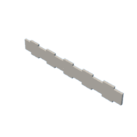
The side pieces of the box will be installed using CA glue. Taking care to arrange the side panels correctly, install them one at a time to the sides of the box bottom. The top and bottom and left and right side panels each have a different number of and different sized tabs that should align with the box bott. One at a time, apply medium CA to the joints of the side pieces that will contact the box bottom panel, then slot them in and hold in place until the glue dries (~20 seconds). Repeat for all sides. Once all sides are installed, apply a bead of thin CA to all joints, allowing it to soak in.
Step 18: Final Testing
The last step before final assembly is testing all electronics to ensure they are working properly. Check the following things:
- Turn the soundboard on using the on/off switch and press all of the buttons.
- Ensure that all buttons trigger a sound from the speaker.
- Note that these sounds can be changed later as long as a sound is produced when the button is pressed.
- Also ensure that all electronics are securely mounted and do not move when the board is shaken.
- Connect the USB jumper on the box panel to a micro usb charger and ensure that the charging light on the battery backpack turns on.
- Finally ensure that the on/off switch does turn the soundboard on and off.
If all of these things work move on to final assembly. If there is an issue with the electronics refer to a previous step and ensure that your soundboard files are formatted correctly. Note that once the box top is installed it cannot be removed without the use of CA debonder so it is very important to do this final check.
Step 19: Final Assembly
The final step is installing the button caps and the box top. Doing this is slightly difficult and I recommend that you get assistance with this step. Follow the steps below.
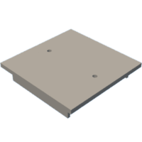
- Flip the box top upside down and place one button cap in each hole in the box top, ensuring the "rails" on the button cap are going vertically.
- With the box top remaining upside down holding all of the button caps in place, flip the electronics assembly over on top of the box top and clamp it together at the edges.
- Now flip the whole assembly back over and ensure that all of the buttons depress easily. You should hear a click when each button is pushed.
- If all buttons are aligned correctly, clamp all four sides of the box and apply a generous amount of thin CA to the joints.
- Leave the box clamped for a few minutes to allow the glue to dry.
- Remove the clamps
Step 20: Final Testing Before Delivery
The final step is to test all functions of the soundboard.
- Press all buttons and ensure they trigger the sound that matches the word or phrase on that button.
- Connect the board to a charger and ensure it charges.
- Check that the on off switch functions properly.
Step 21: Delivery and Conclusions
The final delivery of this AAC soundboard was very successful. When Ethan received the board he immediately took to it, recognizing the similar symbols from his previous board. He was visually delighted when he pressed a button and found out they make sounds. After testing all of the buttons he used the board to inform us that he was both hungry and thirsty.
Since delivery he has used the soundboard often and primarily uses it when it is difficult for whoever is watching him to tell what he wants from other body language and pointing. His parents and school are very pleased with the result and believe they will use it for the foreseeable future.


