Introduction: Control Your Home Appliances With TV Remote!!


Watch the project output video here.
I've found that some people are very lazy to stand up go to the board and press the switch to turn on light or fan or any other appliance but Hey!,Now there is an easier solution. Now you can turn on or off any appliance with just your TV remote. In this instructable I will show you :
- The Parts you need.
- Function of each components.
- How to make the Circuits( The most important one!!!)
- Apply it in your home.
- Some TroubleShooting.
- And some useful links.
So let's get STARTED!!!
Step 1: Gather the Parts!!!


Here all the parts you would need in this Project are mentioned and the links from where you can buy them but I recommend that you should first try to find the components locally because this way you could buy them faster and maybe cheaper but if they are not available locally you can always buy them with the links provided. I always buy everything from ebay 'cause it's the cheapest. For this project you would need:
- An Arduino Uno (Or any other Arduino you have)
- An IR Remote.(You can your TV remote)
- An IR Receiver.
- 5v Relay (x2)
- 1N4007 DIODE (x2)
- Transistor BC547 (x2)
- 1K Resistor (x2)
- PCB Terminals (x2)
- Solderless Breadboard(For prototyping)
- PCB board.
Step 2: What Is IR???


Infrared (IR) is invisible radiant energy, electromagnetic radiation with longer wavelengths than those of visible light, extending from the nominal red edge of the visible spectrum at 700 nanometers (frequency 430 THz) to 1 mm (300 GHz). Most of the thermal radiation emitted by objects near room temperature is infrared. The TV Remote or any other remote produces a burst of IR light of a frequency of 38 KHZ which is also known as Carrier Frequency. Now you must be thinking why 38 KHZ??? It's because a lamp, sun and every other light source produces IR rays so to differentiate from those rays frequency of 38 KHZ is used. The system in our project works like this:
- IR remote sends a burst of IR light which is received by the IR Receiver.
- The IR reciever contains Filter, Amplifier and Demodulator.
- Then the IR Receiver sends a logic output to the arduino and by using the IRRemote.h library and the program we make we can see a unique hexadecimal code for each button we press.
Step 3: Lets Make the Circuit!!!


By the Schematics provided here you can create the circuit. I would recommend making a shield for arduino uno so it could be easy to connects as well as install it anywhere. You want to know how to make Sheilds? Check this. I would also recommend that you should first prototype this circuit on a breadboard and after testing you can head over to the PCB. Don't Forget to Double Check Your Circuit.
Step 4: Which Pin Goes WHERE???
IR RECEIVER DATA - DIGITAL PIN 10 OF ARDUINO
RELAY1 - DIGITAL PIN 8 OF ARDUINO
RELAY2 - DIGITAL PIN 12 OF ARDUINO
Step 5: Get Hex Code for Your Remote Buttons.


- First Download the IRREMOTE Library by this link.
- Now go to Arduino folder where you have installed ARDUINO IDE << libraries << unzip the file here.
- Follow the Schematic and while facing the curved surface of the IR Receiver, Connect PIN 1 to Digital Pin 11, PIN 2 to GROUND and PIN 3 to 5V or VCC
- Now upload the IRRecvDemo from examples of the library and upload the code.
- Now open the Serial monitor and any time you press any button on your remote you would get the hex code.
Step 6: Time for Coding!

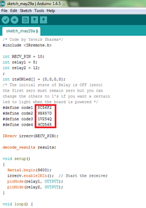
First Download the simple Arduino Program I created. Then instead of numbers 1 2 3 4 as showed in red area write the hex code of the button you want to use in TV remote. Here the code 1 sets your relay 1 on digital pin 8 as HIGH and the code2 sets it as LOW. The code3 sets relay 2 on pin 12 as HIGH and code 4 sets it LOW. In the Second pic you can see that how I changed the values according to the hex code of my buttons in TV remote.
Attachments

Step 7: CAUTION!!! HIGH VOLTAGE!!!

WARNING!!!
Incorrect or Improper use can lead to:
- Serious injuries or Death.
- Physical Damage to the Product.
- Creating dangerous Hazards.
*** I take no responsibility for any of your actions ***
Step 8: How to Use This at Your HOME!!!

Let's say you want to control your light and fan of your bedroom, you can install this circuit on the switch board. Just open the switch board that controls your lights and fans and you will find that two wires are attached to the switch. Just remove those wires from switch and connect them to the PCB terminals and you're done. Super Simple yet Efficient.
Step 9: What's Happening Here???
Here Arduino is Brain of the circuit. When you press any button on your Remote, it sends a burst of IR light at 38KHZ carrier frequency. The IR Receiver receives that light and sends a logic signal to Arduino. Arduino converts those signals to hexadecimal codes which we can see in the serial monitor. Then according to our program, arduino takes those signals as commands and implements it. In our program we have mentioned that if signal of button 1 is received, then relay1 should be set HIGH and so. Here Relay acts as switch. A relay, quite simply, is a small machine consisting of an electromagnet (coil), a switch, and a spring. The spring holds the switch in one position, until a current is passed through the coil. The coil generates a magnetic field which moves the switch. It's that simple. You can use a very small amount of current to activate a relay, and the switch can often handle a lot of current. Here I used a NPN transistor to activate those relays with the Arduino 5v signal because if anything goes WRONG, your transistor would be damaged but your arduino would be saved.
Step 10: TroubleShooting!@#$%

Hmm... Not working as Expected???
Try this Trouble Shooting guide so you can make your project work like a charm!!
- First Check the Code. Have you entered the Wrong Hex code in the program.
- Make sure that the Connections are correct. Using the continuity function of your multimeter check for any wrong connections or short circuits!!!
- Make sure you have working Relays and Arduino.
- Make sure you have placed to diode correctly
- Make sure that your REMOTE is working!!!!
*** If you have any doubts regarding this you can always ask me in the comments below ***
Step 11: Check These Points!!!
- Before testing the circuit, double check all connections with continuity function of multi meter for any wrong connections or short circuits.
- Install the diode between the coils in correct polarity as it will protect our circuit from any reverse current.
- I recommend that before testing the circuit with HIGH AC VOLTAGE, first try it with lower voltage like just a simple led.
- Also never use such appliances that draws more current than your Relay's ratings.
Step 12: What Else Can You Do???


You want to something more, I have some suggestions for you:
- Instead of Arduino uno you can use ATTINY85 which will save a lot of space.
- You can always make a Standalone Arduino on the PCB. Check GreatScott's Tutorial on this.
- You can also make this circuit IOT compatible. You can use ESP8266 WiFi module to control your relays over the internet.
Step 13: Conclusion!!!

This being my first Instructable there may be some mistakes here but that would be awesome if you can give some suggestions in the comments section below. If you like this project please hit the like button and let me know in the comments what you think about this.
YAVNIK SHARMA

Runner Up in the
Automation Contest 2016

Participated in the
First Time Author Contest 2016

Participated in the
Sensors Contest 2016


