Introduction: CubeSat Model With Color Changing LED and Thermistor


In my high school physics class, our assignment was to design, build, and program a functioning model of a CubeSat that will orbit Mars and collect data. This includes programming and wiring an Arduino UNO, designing and building a CubeSat frame, and using the physics principals we've learned in class.
The criteria and constraints we had to work with were that it must weigh less than 1.3Kg, it must be a 10X10X10 cm cube, the frame has to protect the Arduino, and allow us to collect data.
My own group, The CuteSats, chose to use an RGB LED light to indicate the temperature as read by a thermistor.
Step 1: Materials


Parts for the Arduino
- Arduino UNO
- RGB LED
- Thermistor
- 220k resistors x3
- 10,000k resistor x1
- Breadboard
- Wires
- Battery
Parts for CubeSat frame
- 3D printing filament
- Zip-ties
- File for design
Other Tools Used
- File
- Pliers
- 3D Printer
- Velcro
Step 2: Arduino and Coding


- Download Arduino IDE to your computer.
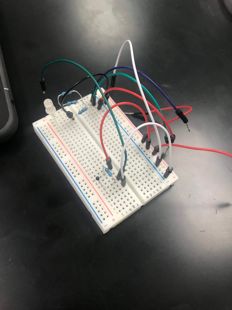
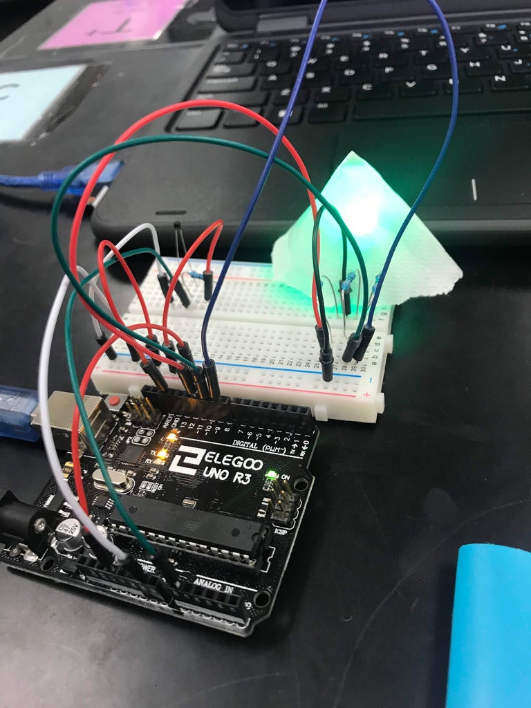
- Wire the breadboard and Arduino according to the diagram.
- Copy the sketch to the IDE and upload to the Arduino.
- Check that the Arduino, breadboard, wires, and battery will fit in the CubeSat frame.
<p>// which analog pin to connect<br>#define THERMISTORPIN A0
// resistance at 25 degrees C
#define THERMISTORNOMINAL 10000
// temp. for nominal resistance (almost always 25 C)
#define TEMPERATURENOMINAL 25
// how many samples to take and average, more takes longer
// but is more 'smooth'
#define NUMSAMPLES 5
// The beta coefficient of the thermistor (usually 3000-4000)
#define BCOEFFICIENT 3950
// the value of the 'other' resistor
#define SERIESRESISTOR 10000    </p><p>int redPin = 11;  // Red Leg of LED,  connected to digital pin 11
 int grnPin = 10; // Green Leg of LED, connected to digital pin 10
 int bluPin = 9; // Blue Leg of LED, connected to digital pin 9

uint16_t samples[NUMSAMPLES];

void setup(void) {
  Serial.begin(9600);
  analogReference(EXTERNAL);</p><p>  pinMode(redPin, OUTPUT);  // Sets the LED pins as outputs
  pinMode(grnPin, OUTPUT);
  pinMode(bluPin, OUTPUT);

}

void loop(void) {
  uint8_t i;
  float average;

  // take N samples in a row, with a slight delay
  for (i=0; i< NUMSAMPLES; i++) {
   samples[i] = analogRead(THERMISTORPIN);
   delay(10);
  }

  // average all the samples out
  average = 0;
  for (i=0; i< NUMSAMPLES; i++) {
     average += samples[i];
  }
  average /= NUMSAMPLES;

  Serial.print("Average analog reading ");
  Serial.println(average);

  // convert the value to resistance
  average = 1023 / average - 1;
  average = SERIESRESISTOR / average;
  Serial.print("Thermistor resistance ");
  Serial.println(average);

  float steinhart;
  steinhart = average / THERMISTORNOMINAL;     // (R/Ro)
  steinhart = log(steinhart);                  // ln(R/Ro)
  steinhart /= BCOEFFICIENT;                   // 1/B * ln(R/Ro)
  steinhart += 1.0 / (TEMPERATURENOMINAL + 273.15); // + (1/To)
  steinhart = 1.0 / steinhart;                 // Invert
  steinhart -= 273.15;                         // convert to C

  Serial.print("Temperature ");
  Serial.print(steinhart);
  Serial.println(" *C");

  delay(1000);</p><p>  if((steinhart) >= 26.2)
  {
   digitalWrite(redPin, HIGH);  // red
   delay(100);

   digitalWrite(grnPin, LOW);
   digitalWrite(bluPin, LOW);

  }

 if(((steinhart) < 26) && (steinhart)>= 23.2)
  {
   digitalWrite(redPin, HIGH);  // yellow
   digitalWrite(grnPin, HIGH);
   delay(100);

   digitalWrite(bluPin, LOW);

  }

  if(((steinhart) < 23) && (steinhart) > 20.2)
  {
   digitalWrite(grnPin, HIGH);  // green
   delay(100);

   digitalWrite(redPin, LOW);
   digitalWrite(bluPin, LOW);

  }

 if(((steinhart) < 20) && ((steinhart) > 17.2))
  {
   digitalWrite(grnPin, HIGH);  // aqua
   digitalWrite(bluPin, HIGH);
   delay(100);

   digitalWrite(redPin, LOW);


  }

  if((steinhart) <= 17)
  {
   digitalWrite(bluPin, HIGH);  // blue
   delay(100);

   digitalWrite(grnPin, LOW);
   digitalWrite(redPin, LOW);
   }
}</p>
Additionally, I've added a visual representation of the color scale according to temperature in Celcius.
Step 3: CubeSat Frame


- Find a premade file of a CubeSat that you want to use, or design and build your own.
- Download appropriate software for the kind of printer/program you are working with.
- Connect to computer and printer.
- Cut out any support pieces left from printing.
- Assemble frame.
Step 4: Results and Troubleshooting

The graph here shows the data we collected on our final test in accordance with the color of the LED during the duration of the test. It started off warm then cooled off a bit and evened out before getting colder at the very end.
A few of the problems we ran into included finding a good 3D design to fit the constraints and purpose. We had problems with other similar sketches and code that wouldn't read the temperature correctly and therefore wasn't displaying the right colors. After lots of trial and error and finally stitching together two separate sketches, we got something simple that works great too.
For anyone replicating this project, make sure to check that you have the right dimensions before sending your file to the printer.