Introduction: DIY 3D-Printed Raspberry Pi Swear Piggy
Pig. No, seriously, pig.
This Instructable gives you a step-by-step guide on how to build your own pig that squeals at you when you swear.
This project is our SIDE project, a year long project that we complete in Ms. Berbawy's Principles of Engineering class.
Special thanks to Ms. Berbawy for her amazing maker space and insight.
Done by: Arjun Ganesan, Eric Ho, Abhinav Valmeti
Supplies
Here are all the materials you will need.
Electronics:
- Raspberry Pi 4 (older versions should perform fine)
- IR Beam Break Sensor
- Speaker (something small if you want it to fit inside the pig)
- Microphone
- I2C LCD Screen, 16x2
- SD Card (8Gb+ recommended)
Other Materials:
- 3d Printing Filament (PLA and NinjaFlex for the stopper)
- Power Supply (most phone chargers will work)
- Jumper Wires
- Super Glue (gel type preferred)
- USB-C cable
- HDMI cable (Raspberry Pi 4 uses micro-HDMI, check to find the right one for you)
Machines Needed:
- 3D Printer (we used Prusa MK3's and Luzbot mini's for NinjaFlex)
- Monitor, Keyboard, and Mouse (to program the Raspberry Pi)
- Soldering Iron (and basic soldering materials)
Step 1: CAD Pig Body
All CADing was done on Fusion 360
1. Form an ellipsoid by creating an ellipse sketch and rotating the profile 360 degrees
→ Preferably create it at the origin to make later steps easier
2. (Optional) Create midplanes and tangent planes throughout the ellipsoid to easier complete later steps
3. Use the shell function to hollow out the shell as there will be electronics and coins going inside
4. Create 4 cylindrical legs of the same length by extruding circle sketches from the body
→ Employ the press pull function if there are hollow holes created in this process
5. Add a mid-plate that runs horizontally through the pig to ensure a separation between coin storage and electronics
6. Add the signature pig snout by extruding a circular sketch off the front of the pig
→ Cut 2 holes into this extrusion symmetrically and side by side to finish the snout
7. Cut a large hole at the bottom of the pig to make room for a stopper to remove coins
→ (Optional) Make it rather large to remove coins quickly
8. Add a hole at the rear end of the pig to connect the microphone and power to the electronics inside
→ Ensure it is larger than the width of the largest wire/cable
Step 2: Designing Intricate Parts
1. Create a hole for the LCD display screen on the side (preferably middle) of the pig body
→ Having an indent in the midplate to support it
2. Make a rectangle sketch with fileted corners and create holes at the top and mid plate to insert/drop coins
→ Ensure the sketch can easily fit in a quarter
3. Using the same sketch, use a shell extrusion to create a coin chute and join it to the midplate
→ The coin chute may be weak so use the rib function to enforce support to prevent it from snapping
4. Add holes towards end of the chute to allow beam break sensors to sense coins that are inserted in the coin chute
→ Ad outlines to hold your beam break sensors
5. (Optional) Add a tail using the coil function at the rear of the pig
6. (Optional) Use form to create ears at the crown of the pig

Here is what the finished CAD looks like:

Piggy
Step 3: 3D Printing the Pig
It is imperative to ensure there are no complications or an insane amount of supports needed when 3D printing to design for printing and manufacturing (Credit to Raj, a Berbawy Makers alum, for the concept)
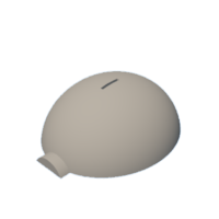
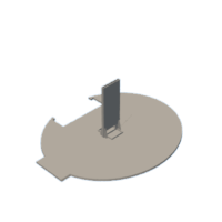
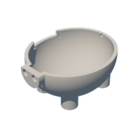
With that in mind we split the pig body into 3 parts to minimize supports needed and to properly 3D print the pig
We removed some unnecessary supports using Torus support blockers on Prusa Slicer
Finally we printed the pig parts in Pink Quantum PLA on a Prusa i3 MK3S+ using the settings above for all pieces.
These finalized parts are shown below and feel free to check out the G-Codes here.
Step 4: Stopper CAD and Print
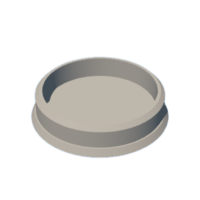
Form a stopper by creating a solid that starts larger than the hole created at the bottom of the pig which becomes smaller across the solid as shown above:
A simpler stopper can be created by lofting three circular sketches together like a sandwich as shown here:

After creating the stopper we used UltiMaker Cura to prepare it for 3D Printing. The settings are listed above:
We printed it with peach colored NinjaFlex filament with a 15% infill density on a Lulzbot Mini2 3D printer.
The STL file for the stopper we used is attached below:
Attachments
Step 5: Setup Raspberry Pi
There are lots of guides online, but here's a short overview of how to setup your Raspberry Pi. Here is the official guide from the Raspberry Pi Foundation.
You will need a separate computer to crate the Raspbian OS image.
- Download the Raspberry Pi Imager. This is the easiest way to create a Raspberry Pi Image.
- Plug in the SD card to the computer and open the imager. If you have files in the SD card, you may want to backup these files as they will be deleted.
- Open the Imager and select the OS you want to use. Use the Lite version if you are using an older Raspberry Pi.
- Click the "Choose SD card" button and select the SD card you wish to flash.
- Let the imager run
After the imager finishes, plug the SD card into your Raspberry Pi and power it on.
Follow the on screen prompts to set up your Raspberry Pi.
Step 6: Electronics
The 2 electronic components of our pig are the LCD and the beam break.
Lets start with the LCD. There are 4 pins on the LCD backpack: SDA, SCK, VCC, GND:
SDA (Serial Data)
SCK (Serial Clock)
VCC (Power)
GND (Ground)
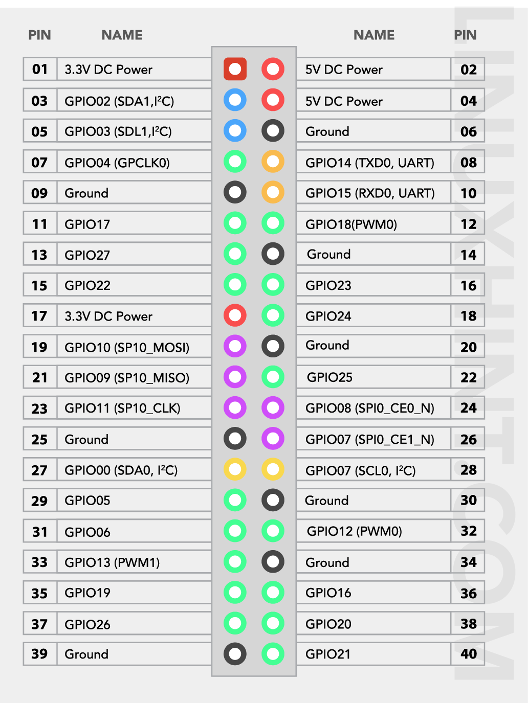
Check the Raspberry PI pinout for the I2C enabled pins. We used GPIO_02 and GPIO_03 pins and 5V and GND pins to wire our LCD. Make sure to remember which pins you used, we will use them later when coding.
Next, lets move on to the beam break.

You'll want something along similar to these. Adjust the dimensions in the CAD to fit the parts which may be different for you.
There are two ends of the IR beam break, the emitter and the receiver. The emitter has two leads to power it, and the receiver has three leads, 2 for power, and the last for data. I found that sometimes the emitter is too powerful and it will overpower the receiver and not be able to detect the coin. I would recommend wiring the emitter to the 3.3V pin (instead of the 5V its speced at) and also put in a 100R resistor.
We just had them as wires but you could also use a perf board or breadboard if you want.
Plug the data pin of the receiver into any standard GPIO pin, and remember which pin you chose. Plug in the remaining pins.
Here's a little sample code you can use to check the beam break. We used GPIO_23 for our beam break data pin.

Step 7: Libraries You Will Need
Here are the libraries that will be needed. I'll go over a few of the more important libraries
import speech_recognition as sr:
This is the Speech Recognition library that is used for speech to text transcription. It supports many models or engines, including the Google Speech Recognition that we will use in this project. Keep in mind that an active internet connection is required.
import I2C_LCD_driver:
This is the LCD driver that is used to drive the LCD. For a more detailed instructions on setup, you should read through this helpful guide on Circuit Basics.
import RPi.GPIO as GPIO:
This is the library that is built into the Raspberry Pi OS. It allows us to use the GPIO pins of PI. This will be used for our bream break.
from pydub.playback import _play_with_simpleaudio:
This is the library that is used for audio playback. One advantage of this library is that it's playback function is threaded (can run in parallel with other processes) and can be stopped with a simple function call.
from pydub import AudioSegment:
This is used to wrap the .wav file into data that can be played by simpleaudio.
Step 8: Speech Recognition
We handle speech recognition through the Speech Recognition library in python.
Through SpeechRecognition, we use the Google Speech API to handle speech-to-text processing. This offloads the processing from the Raspberry Pi, which may struggle to keep up with real-time processing.
Make sure you correctly import all the packages (See Step 7)

We will need to have live speech transcription that continuously takes input and transcribes it.
This works by using the async function listen_in_background (a threaded function) in SpeechRecognition and threading to achieve live recording and transcription at the same time.
We will continuously update the transcription array by recording a stream of bytes, concatenating the new raw audio data to data_queue, a thread-safe queue (can be used by multiple threads, is a FIFO queue)

We pull raw audio data from the queue, making sure to clear the audio buffer if we start a new phrase.
Then, concatenate current audio data with the newest audio data.
Next, we convert raw audio data into wav data and then we can pass it into Google Speech Recognition with some basic error handling.
Using the phrase_complete variable, we can add new Strings to the transcription array.

Now that Google has handled all the transcription and it is placed conveniently in our array, we can check if any swear words were detected, compared to our list of swear words. It loops through each string in the array.
It just parses through the csv list of swear words that you can configure yourself.
If a swear word from the transcription matches the swear words from the list, the pig will use simpleaudio to play the wav files. It will also update the counters for swear words. The sounds are produced by running a random function and matching the number with one of the many squealing tracks the pig already has.
You can record your own audio using .wav files. Make sure to put the files in the same directory as the file so it can be accessed. Also make sure to update the names of the files in the code. We have a whole bunch of annoying sounds from people all around the classroom. We've attached a sample sound file that we enjoyed.
Attachments
Step 9: Increase Swear/Coin Count
When the user inputs a coin, the coin will pass through the chute and break the beam break sensor. The previously TRUE beam break sensor will produce a FALSE result. The beam break works by detecting state changes instead of always checking its value. This is much more efficient.
The program will then cease the squealing noises being played. It will increment the coin counters and break back into the loop.
Make sure the speakers and microphone are plugged in. You may have problems with playback and devices, just Google any errors that you get. Many of these are problems with Linux, but luckily, there is a lot of support online. Don't be afraid to ask in forums.
Step 10: Assembly
Start by gluing the midplate to the bottom half of the pig. Let the glue set. In the meantime, go check that all the electronics work. Add and remove the stopper as you please.
Next, glue down the beam breaks into their respective spots. Make sure they are in the right direction and point into each other. Use gaffers tape to hold them down. Plug in the speaker and hold it down. Slide the LCD screen into the cutout on the pig. The fit may not be perfect based on the tolerances of your printer. If you need to, sand or dremel it until it fits.
Next, route the wire for the speaker and the wire for power through the hole in the rear-end of the pig. Dremel until the both wires can be passed through. You can also pass through display and keyboard cables.
Finally, use gaffers tape to hold down the Pi to prevent it from shaking inside.
The top is removable, and is fit in with the coin chute. You will need to start the program each time (looking to get it to run on boot in Linux) Keep in mind that it is quite fragile. Be careful when putting it on and taking it off. We hope to reinforce the coin chute in future iterations.
Closed pig with electronics inside:

Step 11: Have Fun Swearing at the Pig
Once you are done building the pig, you can use it to catch people swearing. The hideous noises resembling a pig will compel your friends to input coins to stop it.
Here's our G-rated demonstration video on YouTube.


