Introduction: DIY Bluetooth Controlled Hovercraft

We are team “Unknown” from the University of Michigan - Shanghai Jiao Tong University Joint Institute. During the last month, we built a hovercraft for racing.
This manual is an instruction on how to build this hovercraft. If you are interested in building one hovercraft for racing or just for entertainment, you can refer to our procedures. The building needs some basic knowledge on mechanical design and controlling circuits. The expected time from getting all the materials to completing the whole hovercraft is about one week.
Step 1: Prepare the Materials and Tools


The PDF file shows all the materials and tools we needed in the building process. All the links are from www.taobao.com and www.tmall.com which are convenient for Chinese users. You may also find similar materials on www.ebay.com by searching the names and the photos in the links we offered. The prices may be slightly different between the Chinese websites and Ebay.com.
Some specific tools and electronic components:
Figure 1.1: Electronic speed controllers
Figure 1.2: V-shape wire
Figure 1.3: Sponge
Figure 1.4: UHU glue
Figure 1.5: Copper cylinders, screws and shims
Figure 1.6: The motor frame
Prepare the Acrylic board
Download the Auto CAD software and draw the blueprint of the body boards according to the sizes in the diagram. Cut a 1mm Acrylic board with the CAD shown below with a laser-cutting machine.(Figure 7)
Cut a 3mm Acrylic board with the CAD shown below with a laser-cutting machine.(Figure 8) The Acrylic board should look like Figure 9 after cutting.
Attachments

Step 2: Make the Body of the Hovercraft


1. Cut the wood bars
Cut the 20mm*20mm wood bars into two 25cm long bars and two 20cm long bars. Cut the 25cm bars and the 20cm bars in half along the length direction. They are now 20mm*10mm*25cm and 20mm*10mm*20cm.(Figure 2.1, Figure 2.2)
2. Make the skirt
Straighten the blue sponge and mark two points so that the distance between them is 27cm. Draw a line with 45 degrees according to the length direction. Cut along the line with scissors as shown in the graph. Repeat the above operations for another one 27cm sponge and anothor two 20cm sponge. (Figure 2.3)
3. Assemble the main body
Stick the 20mm*20cm surfaces of the two 20cm wood bars to the two 20cm sponge with UHU glue. Stick the 20mm*25cm surfaces of the two 25cm wood bars to the two 27cm sponge with UHU glue. (Figure 2.4)
Stick the angles with UHU glue to combine the four parts.(Figure 2.5, Figure 2.6)
Stick the 10mm*20cm surfaces of the two 20cm wood bars to the two shorter sides of the big Acrylic board with UHU glue. Stick the 10mm*20cm surfaces of the two 25cm wood bars to the two longer sides of the big Acrylic board with UHU glue. (Figure 2.7)
Stick the edges of the adjacent sponges several with UHU glue. The completed structure should look like this one in Figure 2.8.
Step 3: Build the Steering Structure of the Propulsive Fan


1. Fix the propeller to the motor
Put the components through the motor axle in the order of screw ring, propeller and the screw cap. Screw the screw cap. Make sure it is tightened to ensure safety. (Figure 3.1)
2. Fix the servo to the board
Drill four holes on the cross component of the servo corresponding to the positions of the four holes on the motor frame. Fix the cross component to the servo and the motor frame to the cross component with screws and screw caps. Use screws and screw caps to fix the servo to the small board.(Figure 3.2, Figure 3.3)
3. Fix the pillars to the board
Fix the four 40mm copper pillars to the board with screws. Place a gasket between each copper pillar and the board. Make sure the motor and the pillars are on the opposite sides. (Figure 3.4)
4. Fix the motor to the servo
Fix the motor to the servo with screws. (Figure 3.5)
Step 4: Build the Structure of the Lifting Fan


1. Cut out two wood boards to make the frames of the lifting fan
Draw two 8cm*8cm square on the wood board. Draw a circle of 6.7cm diameter on one square and a circle of 6.4cm diameter on another. Cut along the lines with a knife. (Figure 4.1)
2. Fix the lifting fan with the two wood frames
Put the lifting fan through two wood frames, the one with a big hole first and the other next. Push the two frames to the corresponding ends. Use four 20mm copper pillars to fix two frames together. (Figure 4.2, Figure 4.3)
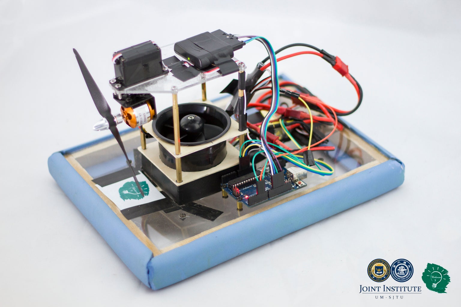
Step 5: Assemble the Power Tower


1. Use copper pillars to connect the structure of the propulsive fan with the structure of the lifting fan.
Aim the four copper pillars in the lifting part at the four pillars in the propulsion part. Screw the copper pillars in the lifting part to the propulsion part. Screw four 15mm copper cylinders under the lifting part. Stick tape around the four 15mm copper pillars.
2. Combine the power tower with the main body
Point the propeller to the back of the hovercraft. Fix the power tower to the main body with screws.
Step 6: Program the Arduino Board

Download the Arduino programming software from Arduino’s Homepage ( www.arduino.cc).
You also need an additional library for PS2 controller receiver, which is available here with instructions:
http://www.geek-workshop.com/thread-172-1-1.html(Chinese)
Write the propulsion program, lifting program and steering program. (The code we used is attached below.)
Upload the Arduino programs to the Arduino board.
Attachments
Step 7: Connect the Circuit


1. Connect the Bluetooth receiver with the Arduino board
Connect the Bluetooth receiver with the Arduino board with six male-to-female Dupont wires.
The following table shows how to connect.(Figure 7.1, Figure 7.2)
Bluetooth(From the left): 1 , 2 , 4 , 5 , 6 , 7
Arduino pin: 12 , ~11 , GND , 3.3v , ~10 , 13
2. Connect the electronic speed controllers with the motors
Connect the brushless motor with one of the electronic speed controllers and the lifting fan with another electronic speed controller by connecting wires with same colors together. Connect the two electronic speed controllers with a V-shape wire.
Fix the two electronic speed controllers as indicated in Figure 7.3.
3. Connect the electronic speed controllers with the Arduino board
Weld three male-to-male Dupont wires at one point and fix it with insulating tape. (Figure 7.4)
Connect one end of the connected Dupont wires to the GND pin on the Arduino board. Attach the other two ends to the two black wires of the electronic speed controllers.
Connect the white wire of the electronic speed controllers that is connected with the lifting fan with the pin 5 on the Arduino board with a male-to-male Dupont wire.
Connect the white wire of the electronic speed controllers that is connected with the brushless motor with the pin 6 on the Arduino board using a male-to-male Dupont wire.
4. Use a V-shape wire to power the motors and the Arduino board
Warning: For safety concerns, do not attach the power wire to the Arduino board in this step. (Figure 7.5)
5. Connect the servo with the Arduino board
Use three male-to-male Dupont wires to connect the three wires of the servo to the Arduino board.
Servo: Red , White , Black
Arduino pin: 5v , 4 , GND
(Figure 7.6)
Step 8: Fix the Arduino Board, Bluetooth Receiver and Prefix Battery

1. Fix the Bluetooth receiver on the top of the power tower with tape.
2. Fix the Arduino board on the hovercraft body with three groups of copper pillars, screws and screw caps.
3. Fix the battery at the center of the hovercraft body near the power tower with tape.
Step 9: Balance the Weight of the Hovercraft
Calibrate to make sure that the center of gravity is near the geometric center of the hovercraft body
Start the lifting fan, put the battery on one position of the Acrylic board and push the hovercraft horizontally. Observe whether the hovercraft is sliding in a straight line. If not, shift the battery’s position in the direction against which the hovercraft is sliding until the hovercraft can slide in a straight line. Mark the position of the battery. Put the battery on the same position every time.
Step 10: Finish

Connect the Arduino board and the motors to the battery. Press the “start” button on the PS2 handle to start the hovercraft. The operation manual is shown in Figure 10.2, and it is also attached as the PDF file.


