Introduction: DIY Homework Writing Machine
In this Instructable, I'll show you how to create a completely functional 3D-printed writing machine for your science fair project at school or college. This project was created as part of my second-year engineering project at Gujarat's Chandubhai S. Patel Institute of Technology (CSPIT). I also make this video for my YouTube channel "Creativity Buzz".
To design this writing instrument, I used Autodesk Fusion 360. There are many different kinds of writing robots, but in this lesson, I create a corexy writing machine. Making use of this will teach you everything there is to know about this writing robot.
All of the 3D printed parts are attached stages in the .stl file. You can download this and edit it in Autodesk Fusion 360 as necessary.
Supplies
There are three types of products need to make this Writing Machine.
1) Electrical Materials
2) Hardware Materials
3) Software and Firmware
1) Electrical Materials
- 3D Printer https://3dflyingbear.com/
- Computer
- Arduino Uno (1 pc) https://amzn.to/3GtBDFT
- CNC Shield V3 Expansion board (1 pc) https://amzn.to/3GtBDFT
- A4988 Stepper Motor Driver (2 pcs) https://amzn.to/3GtBDFT
- Nema 17 Stepper Motor ( 2 pcs) https://amzn.to/3KjIoeN
- SG90 Servo Motor (1 pc ) https://amzn.to/3ZU7arD
- 12 Volt 2 A Adapter
- 2 pin Short Jumper ( 6 pcs )
2) Hardware Materials
- 8 mm Threaded Rod 42 cm long and Nut (2 pcs)
- 8 mm Plain Steel Rod 35 cm long (2 pcs)
- 8 mm Plain Steel Rod 27.5 cm long (2 pcs)
- 6mm Plain Steel Rod 6.5 cm long (2 pcs)
- 7mm Spring @ 20 Rs (1 pc)
- LM8UU Slider bearing (8 pcs) https://amzn.to/3KnvtIP
- LM6UU Slider bearing (2 pcs) https://amzn.to/40TpjHk
- 623ZZ 10x4x3 mm bearing (10 pcs)
- Stepper motor Pulley GT2 (2 pcs)
- GT2 6mm Belt 2 meter https://amzn.to/3ZWBTEp
- 3mm + Nut and Bolt ( 16mm , 40 mm length )
3) Software
- Autodesk Fusion 360 ( We use this software to design 3d .stl parts to use in 3d printer to make plastic parts )https://www.autodesk.in/products/fusion-360/
- Ultimate cura ( We use this software for slice .stl file to gcode for use in 3d printer ) https://ultimaker.com/software/ultimaker-cura/
- Arduino IDE ( For Install corexy Firmware to Arduino Uno ) https://www.arduino.cc/en/software
- Inkscape version 0.92 ( For make gcode file for writing or drawing or photo to use in universal gcode sender) https://inkscape.org/release/inkscape-0.92/?latest=1
- Universal gcode sender ( Import gcode file which exported from Inkscape and give command to writing machine) https://winder.github.io/ugs_website/download/
Step 1: Make Plastic Parts
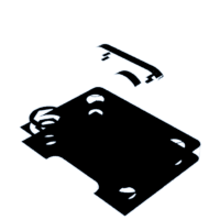
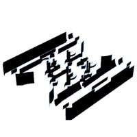
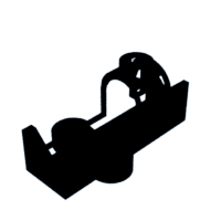
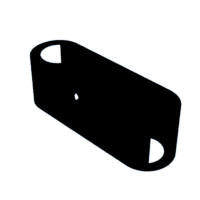
We design plastic parts in Autodesk Fusion 360 and export them as .stl files. All .stl files that are attached to steps that use them. Import the stl files into the ultimaker cura slicer software and adjust the settings for the walls and nozzles you require.
Then, export the gcode file to a memory card and print it using PLA filament on a 3D printer. Make every 3D printed object step by step. To assemble this writing machine, we need 10 3D-printed components. The total weight is around 250 grammes.
Step 2: Make Y Axis Slider
Take two 42 cm long 8 mm threaded rods, 8 mm nuts, and the stepper motor holder after all the 3D-printed parts have been completed printing. Then, as shown in the picture, passing this threaded road from the bottom holes in the stepper motor holder. Next, insert threaded rods from the opposite end of the second stepper motor holder.
Fix two nuts on the second end of the threaded rods after passing them through both stepper motor holders.
Step 3: Added Stepper Motors
Next, take two stepper motors and insert them into the stepper motor holders' casing. Then tighten every screw on the holder joint and stepper motor.
Take two 8 mm plain steel rods that are 35 cm long and pass them through the stepper motor holder's top holes.
If you need to write on a huge scale, you can use long steel rods, although large highways reduce the quality of your writing.
Step 4: Middle Slider for the X- Axis and Y-axes
After creating the y axis, create the middle slider that connects the x and y axes.
Take two middle slider plastic 3d printed parts for this, one additional 3d printed part, LM8UU Slider bearing (8 pieces), 623ZZ 10x4x3 mm bearing (8 pieces), and 40mm x 3mm bolts and nuts.
Place one 3D-printed slider object four LM8UU Slider bearings, and Attaché the other 3D-printed slider object four LM8UU Slider bearings. Next, insert four 40mm long bolts into the holes shown in the illustration. From the other side, attach two 623ZZ bearings to these bolts. Then attach all bolts from the opposite side and attach the middle 3D-printed part to the other middle part. Then secure the middle slider with the final four 40mm bolts.
After creating the middle slider, take the Y axis and remove half of the plain rod, and run the middle slider through this. After that, reattach the plain rods to the stepper motor holder.
Step 5: Pen Holder
The pen holder needs to be built once the Y-axis has been constructed.
Two 6.5 cm long 6mm plain steel rods, two LM6UU slider bearings, and a 7mm spring are the components you'll need to assemble a penholder using 3D printed materials. As shown in the picture, place two LM6UU bearings into the two holes in the grey 3D printed portion. Then, using two 6 mm plain rods, pass them through the wooden 3D-printed components of the pen holder as shown in the third picture. Place a 7 mm spring between the holder and bearing for the second rod while passing the first rod directly.
Use 16-mm bolts and nuts to attach the red pen stand to the grey 3D-printed portion.
Step 6: Make X Axis
Two 27.5 cm long 8 mm plain steel rods, a pen holder, and a 3D printed belt end portion are required to make the X axis.
Attach two 8mm steel rods to the belt end 3D printed item as shown in the picture. After that, move the Y axis' middle slider over this structure. Fix the pen holder to the second end of the steel rod after that. Fix a permanent junction with two 16mm bolts.
Attachments
Step 7: Pulley and Roller
Then insert two 623ZZ bearings into the pen holder and fix them using a 40-mm bolt.
Get two GT2 stepper motor pulleys and attach each one individually to the stepper motor shaft.
Step 8: Run GT2 Belt
Take a 2-meter GT2 belt and attach one end to the wooden belt holder portion that was 3D printed.
Next, pass the second end of the GT2 belt through the 623ZZ bearing on the middle slider, the stepper motor GT2 pulley, the 623ZZ bearing on the pen holder, the GT2 pulley, and the 623ZZ bearing on the middle slider before attaching the second end to the belt holder 3D printed component as shown in the pictures.
Step 9: Make Controller Box
Arduino Uno, CNC Shield V3 Expansion board, two A4988 Stepper Motor Driver, and six short jumpers are required to create the controller box.
Take a controller box that was 3D printed and mount an Arduino Uno on it. On the Arduino Uno, attach the CNC Shield V3 Expansion board as shown in the picture. Then, as shown in the diagram, take a short jumper and place it on the CNC shield. Place the final two A4988 drivers into the CNC mill as shown in the illustration.
Attachments
Step 10: Servo Motor and Wiring
The final step in building a writing machine with hardware and electrical components is this.
From the back, insert the SG90 servo motor into the pen holder's cavity. After that, link the stepper motor wire to the two motors. Take the controller box and insert it through the bottom threaded rods of the Y-axis. Then connect the SG90 servo motor wire and the stepper motor wire to the controller box.
Step 11: Firmware Installation
- Download the Corexy firmware using this link.
- https://github.com/jamescarruthers/PlotterXY
Download all of the software listed in this instructable's supply step.
Next, use a USB pin to connect an Arduino Uno to a computer. Next, launch the Arduino IDE software on your computer and choose the Arduino Uno board and Port.
Then use the file - open menu to open firmware in the Arduino IDE. then upload Arduino Uno with firmware.
Create a design in the Inkscape programme, then export it to the Universal Gcode Sender programme. then press "start" to begin writing on paper.
Step 12: Writing on Paper
Fix the pen in the pen holder upside down, 4 mm from the paper. Then press "Start" to write on paper.
You can write or draw any image on this writing machine.

Participated in the
3D Printing Student Design Challenge


