Introduction: IR MultiTouch Sensors for Augmenting Objects and Human Skin


I've been building custom IR sensing solutions for a while now. These include proximity sensors, object detection sensors and multit-touch sensors. The intent behind this instructable is to share some of the experiences I've collected in desinging these custom sensors. Ideally this will help you in coming up with your own custom solutions.
Most touch sensing solutions I see use either capacitive or resistive solutions. While these work just fine for most applications, sometimes there are situations where these are not practical. Examples include environments where there is too much electromagnetic noise for reliable capacitive sensing, or if you want to sense touch on surfaces which are difficult to access, such as the human body. In some situations IR sensors also have benefits over capacitive and resistive technologies, as they can simultaneously act as depth sensor and touch sensor, giving you a much better idea of what is actually going on.
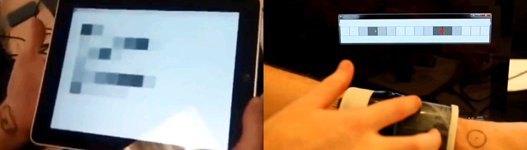
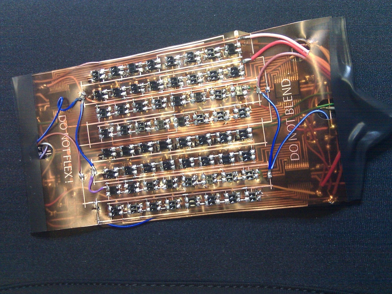
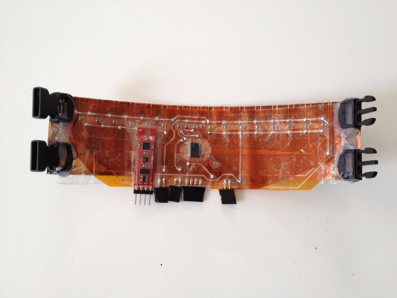
The image above you can see a two dimensional matrix of IR emitters and receivers acting as a depth camera on the back of a tablet (providing me with a 3D representation of whats happening) and a linear array of IR emitters and receivers acting as a 2D multitouch sensor.
This is a very high level overview, because I am trying to keep this general purpose. Things I assume you either already know or will learn somewhere else:
- measure a voltage using an Arduino or standalone microcontroller
- design and implement a circuit with a method of your choice
- interpret your sensor data (depending on how complex your sensor is, some basic computer vision knowledge can be useful)
If you find that this is too high level, let me know and I can try and give more specific examples, however, I am afraid that such examples might no longer be generalizable.
Limitations:
- the methods I show here work poorly in direct sunlight. They are also probably not something you want to have in an actual product as they are relatively power hungry and expensive (if someone tells you about a cheap low-power IR sensor - ask them how it compares to a capacitive sensor...). These sensors are *great* for prototypes and experimentation though...
This instructable is based off work I presented at Augmented Human 2015. You can read the paper, look at the poster or check out the video:
https://www.youtube.com/watch?v=LkZcak3Eh8U
Step 1: Understand the Principles

What is infrared (IR)?
Infrared is electromagnetic radiation outside of the visible spectrum. The visible spectrum of electromagnetic radiation (visible light in all its colors), borders on Ultra Violet as its wavelength becomes too short for us to see it as light, and Infrared when the wavelength is too long for us to see it. When speaking of Infrared (IR) it is useful to distinguish between Near IR and Far IR. A simplified way of understanding the difference is that Near IR is invisible light and Far IR is heat. When I speak of IR I refer to near IR (specifically frequencies between 700nm and 1400nm as most components you can find deal with wavelengths within that range).
How can we use IR to sense things?
Basically we need three elements, a thing that emits IR (for example an LED), the thing we want to measure or detect (for example a finger), and a thing which detects IR (for example a phototransistor).
In the schematic above, on the left, is a voltage limiting resistor and an IR LED (note, that I gave the resistor an arbitrary value. You will need to check the datasheet of your LED and calculate yourself what resistor you need).
On the right you find a phototransistor connected to ground, an analog input and via a pull-down resistor (again, arbitrary value) to power. In this setup, you will measure 5V when the photo-transistor is not detecting any IR. Once IR hits the photo-transistor, the voltage will gradually drop to 0 when the transistor is saturated with IR.
Note that different materials reflect IR in different intensities, the amount a given material can reflect IR is sometimes very difficult to tell based on intuition alone. For example, a page covered with black print from a wax printer reflects most IR, while black electric tape does not reflect it at all (or was it the other way around? its been a while since I discovered this for myself). If you are encountering weird behavior, looking at your setup with an IR camera can reveal a lot about whats going on.
Objects also reflect more IR when they are close to emitter and receiver and less when they are far away. This means that:
If you know the material, you can tell how far away an object is
or
If you know how far away an object is, you can infer what material it can be
Step 2: Understand Your Problem

Define precisely for yourself what you are interested in sensing. Don't think about it in terms of sensor yet. Think about it in terms of the event you wish to capture: What state is your system in when you do not wish to detect anything? What state is the system in when you *do* wish to detect something? What has changed? How does that change reflect in something I can measure with a IR sensor?
For example, I was building an interactive wristband and was interested to measure hand movements for gesture control. I wanted to measure the movements of the wrist. What happens when the wrist moves? Muscles activate. She shape and diameter of my lower arm change as different tendons are stretched. The distance between my knuckles and the wrist changes. The orientation of my hand relative to the wristband changes.
I could measure muscle activity (using something like Thalmic Labs MYO). I could probably measure the changes in shape and diameter with an array of pressure sensors or capacitive sensors wrapped around my arm (possibly even with IR). I could measure the change in distance between the knuckles and the wrist with a stretch sensor.
The relative orientation of the hand changing means that a line pointing outward from the wristband, parallel to my hand is sometimes unoccluded, but sometimes is occluded by the hand in varying degrees. *This* is something I can measure with IR. I ended up using three sensors, one underneath the pinky, one underneath the palm of the hand and one underneath the knuckles. Check it out:
What you measure is usually a subset or an effect of the action you are actually interested in capturing. Conceptually breaking down the thing you wish to measure into all the different changes that occur, will provide you with various different ways of measuring something. Try to find the simplest method available to you that will get the job done.
(EDIT: I added the link to the pressure sensor paper. Did not know about it at the time of writing this.)
Step 3: Chose Your Components


Depending on what you wish to measure you will have to select different components. There is usually a trade off between precision and sensing distance: large and powerful emitters allow you to sense things further away, but you will also need to move them further away from your photo-transistors, so you have a lower spacial resolution in the other dimensions.
When picking your own items, its probably a good idea to be familiar with how others work. Sparkfun sells some of my favorite IR sensors. The sharp series is pretty cool for depth and gesture sensing: https://www.sparkfun.com/products/242
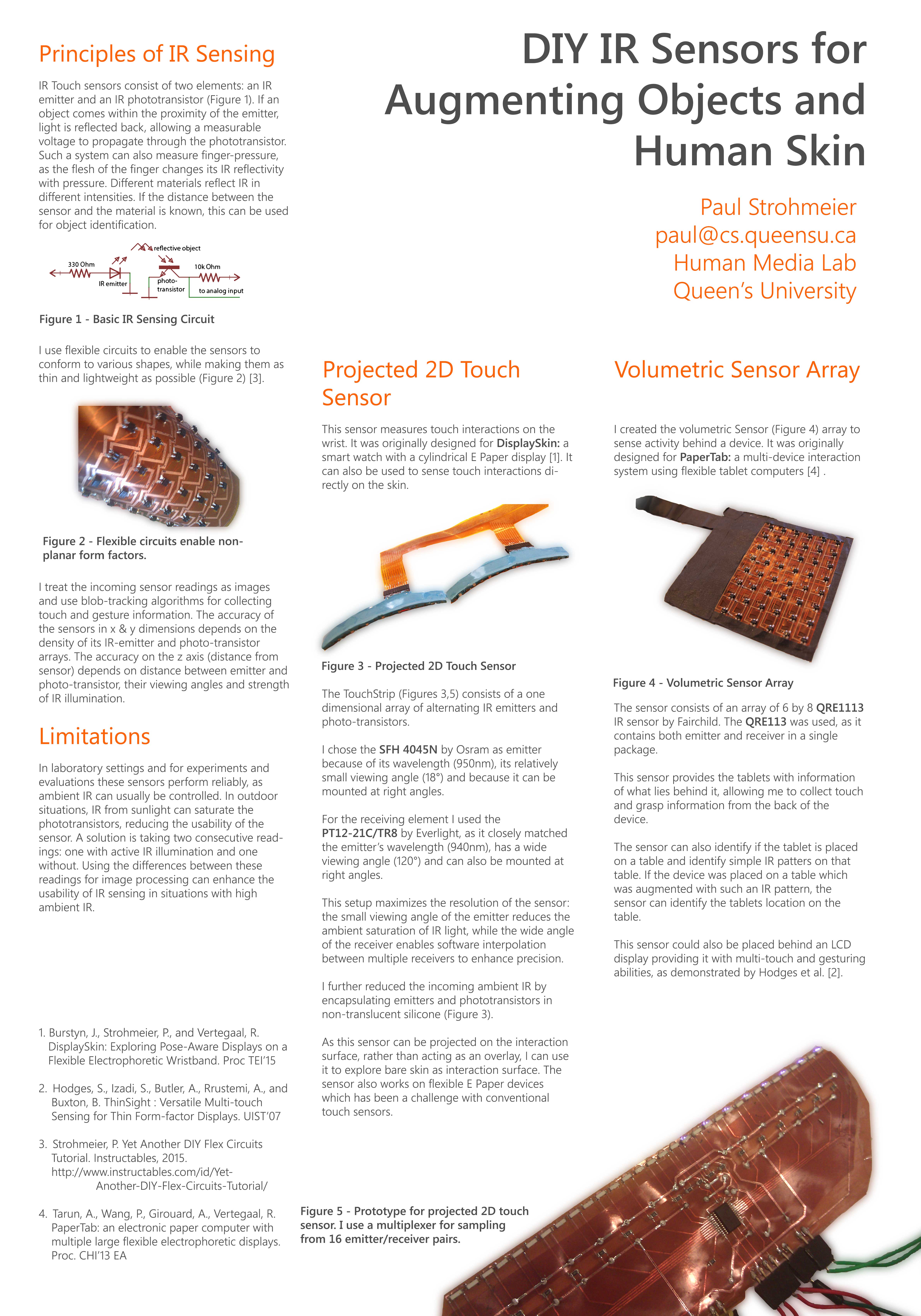
These QRE1113 that Sparkfun uses in their line-sensors are super versatile - I've used them in many different projects (including the gesture sensor I showed you in the previous step, and the 2d sensor array you can see below): https://www.sparkfun.com/products/9453
If you need something more specific Digikey is a good place to start searching. Find a phototransistor (http://www.digikey.dk/product-search/en/sensors-tr...) and a emitter (http://www.digikey.dk/product-search/en?keywords=i...) using these links. The two main things to consider are component size to fit your application and matching the frequency of emitter and phototransistor.
I can't really tell you which components to chose, as each use-case will probably have different constraints making different components the preferred choice. However, the QRE1113 is probably a good place to stat. One of its big benefits is that while it combines phototransistor and emitter in the same package, unlike the sharp components you have full control over how you use them. You can integrate them into your electrical circuit as if they were individual components, allow you to, for example, pulse the emitter, and sampling the phototransistor with emitter on and emitter off alternately. I used these for the two dimensional arrays you see above.
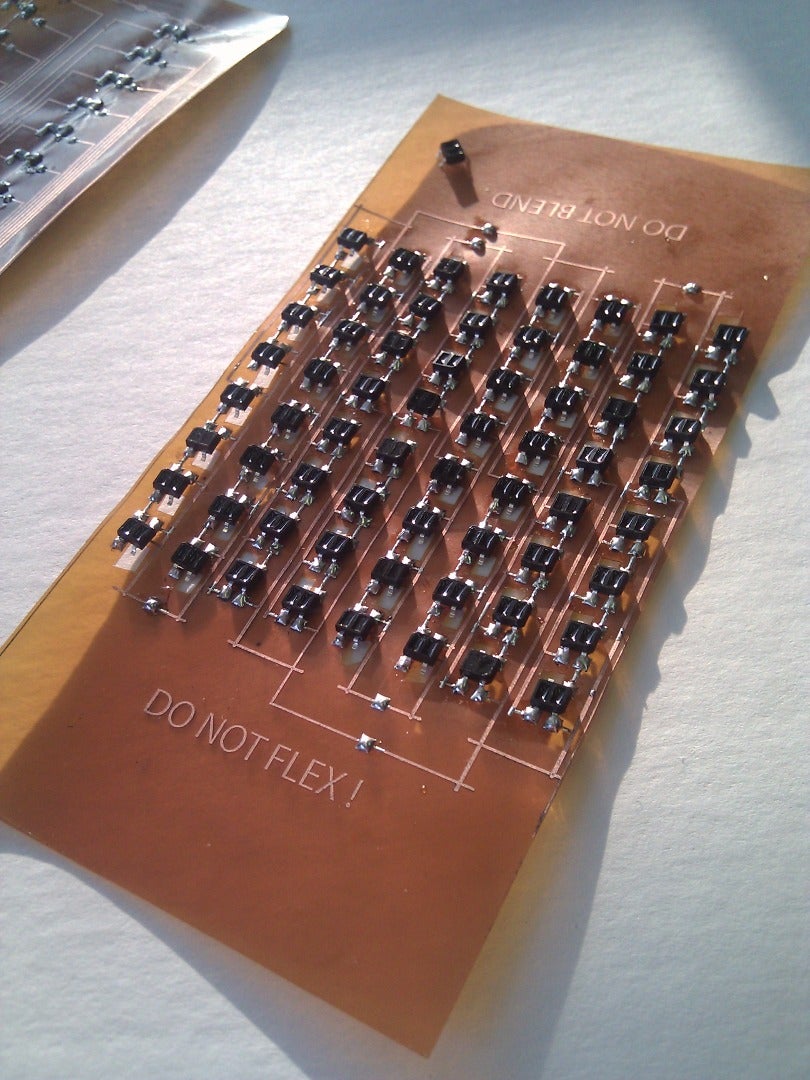
A combination of emitter and receiver I have had good success with is using the SFH 4045N by Osram as emitter and the PT12-21C/TR8 by Everlight as phototransistor. They match their wavelengths nicely, and I found that the combination of the small viewing angle of the emitter (18°) with the large vieweing angle of the receiver (120°) works well. I use these in the linear sensors you can see above. It is possible that a smaller viewing angle for the receiver might be better, as I rely relatively strongly on encapsulating for preventing direct cross-talk between emitter and phototransistor, but this is what I ended up using for a series of sensors.
Step 4: Design and Build Your Circuit
If all you have is one emitter and one photo-transistor you can basically follow the schematic I posted abode. If you are dealing with multiple emitters and phototransistors you are basically designing two circuits and LED array and a phototransistor array.
For the LED's you can check out some of the online LED schematic generator for suggestions on how to connect things: http://led.linear1.org/led.wiz or http://www.ledcalc.net/
For the phototransistors you are basically stuck creating an individual circuit for each. However, you can use multiplexers to make your life easier and also to read values from more sensors than you have analog inputs on your Arduino or other microcontroller. I personally really like the CD74HC4067. Here is a nice write-up on how to use it: http://bildr.org/2011/02/cd74hc4067-arduino/ (If you look carefully in the above images, you will see that I am using the CD74HC4067 there as well)
I'm not going to get into the how-to's of building this. Sparkfun has an extremely well put together tutorial on the soldiering aspects of things: https://www.sparkfun.com/tutorials/category/2
I posted a tutorial on the flex-circuits you see all over this tutorial on instructables some time ago: https://www.instructables.com/id/Yet-Another-DIY-Fl...
Note however, that I only use flex-circuits, because that's just my thing. There is no special reason for that choice. Use whatever method you prefer.
I've added a video of me assembling a linear IR sensor.
Step 5: Know How to Debug Your Circuit


Fixing problems when dealing with invisible effects can sometimes be very frustrating. The obvious solution is to get yourself an IR camera (https://www.instructables.com/id/turn-webcam-to-IR-sensitive-camera/). The black and white image was taken with such a DIY IR camera - a regular camera would not have shown me the LEDs lit up brightly as they are. Another option (and often the easier option) is to find a camera with a poor IR filter. Most pre ~2013 smartphone camera will do the trick. The color image above was taken with a high-quality camera with a good IR filter. You see that the camera taking the picture does not capture any light emitting from the sensor, while the smartphone clearly shows the LEDs emitting light.
Step 6: Optimize Your Sensor and Environment


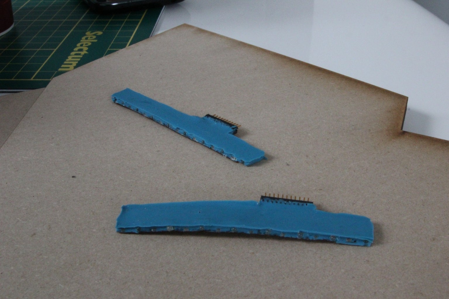

As I pointed out at the beginning, direct sunlight makes these sensors close to useless. Another thing which can be a problem is IR bleeding through directly from emitter to receiver (this is especially true if you use wide FOV components. A way to mitigate and possibly completely remove these effects is to create your own packaging.
I've encapsulated my sensors using regular off-the-shelve casting silicone. I use play-dough for creating a mold, and then simply fill it up with silicone, as you can see in the above images. This dramatically increases the quality of the sensor readings.
It also has the side effect of creating really nice-looking components.
*
I think I've covered the basics of my workflow. Please help me improve this instrucable by asking questions. I will update this, once I have a better idea of what parts people want more info on.