

Introduction: DIY IoT Smart Doorbell


I live in a large basement apartment, where reception is problematic, together with the fact that I wear headphones a lot and have no working doorbell made me reach one conclusion - I should make doorbell that notifies me when someone is at the door and who, while also letting the guest know that I know they have arrived, sounds like a cool IoT project!
The doorbell awaits a password to be entered by a guest, once a password is entered and verified, I will get a Push notification to my phone (via local network) with a message and a link, the link can be anything you choose (for some people I chose a song, others a photo, anything that comes to your mind).
Additionally, there will be a message displayed on an LED matrix which shows: “HI <NAME OF GUEST> 🙂”, (I added a heart to replace the smiley face in case it's my girlfriend at the door :D), so your guests will know that you are aware of their arrival, a few smart tweaks were added to make the code generic and scale to more features, there is also a reset option if a guest misclicked their password.
Features:
- A passcode that is made up of 5 buttons (total 3125 password combinations) - can handle heavy duty hosts!
- Easily add\edit\delete the guests list - names, passcodes, customize notification info sent to your phone and change the message presented at your door.
- Reset try in case of a misclick! (holding the first two buttons for 3 seconds)
- Easily expand the capability and features of your doorbell - email notifications, LED colors, additional buttons, and more!
- Add recipients - easily add more recipients to handling the arrival of guests and share the fun!
Supplies
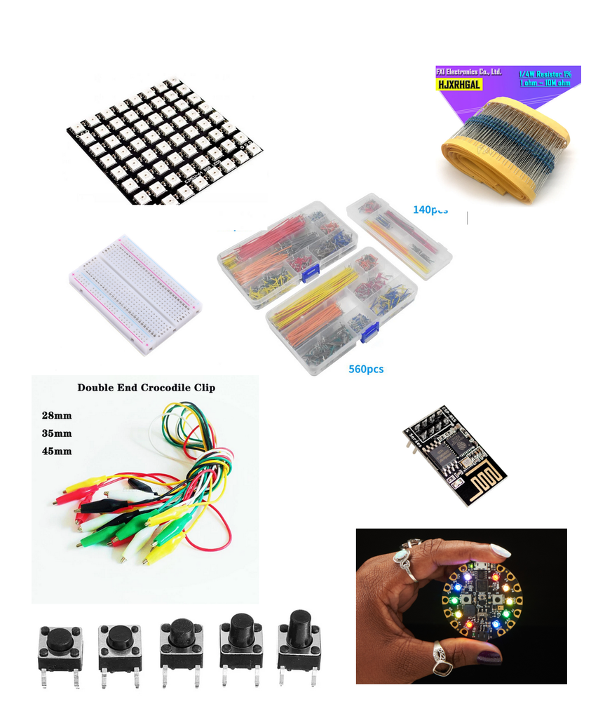
- Electronics: (Skip some if you can connect wires with a soldering iron)
- Circuit Playground Express Board (or some other device with proper reconfigurations)
- ESP8266 WiFi Model (or other compatible WiFi shield)
- 64 LED matrix
- Breadboard
- Breadboard buttons
- Breadboard wires
- Breadboard resistors
- Alligator clips (8 should do)
- Boxing: Any material that you can think of to make the box, the only thing is - design it after you're done, so you have the correct dimensions needed, if you want to use my (temporary) boxing, just have some sort of cardboard, electrical tape, and maybe some harder material like wood.
Step 1: Software and Hardware Prerequisites:
- A stable internet connection is needed where the smartbell will be placed.
- Project Code and design logic
- Introduction to Adafruit Circuit Playground
- Connecting Adafruit Circuit Playground Express to WiFi
- A make/Integromat account and mobile application
- Installing Node-Red
- Installing Mosquitto MQTT Broker (any other compatible MQTT Broker will do)
- Installing Arduino IDE (any other IDE can do)
Step 2: Design and Setup

The (very) abstract design shows the entire flow starting from a guest inputting a password all the way through the final stage where the admin gets the notification, with various technologies and their part. please make sure to:
- Configure and install your Circuit Playground Express board (or other board) with the WiFi shield (mine is configured on pins A7 and A8) and Install some IDE via the links provided above, make sure the ports, necessary libraries, modules and files are properly configured, and that you are getting an internet connection
- Clone the project code repo to your local machine
Step 3: Electronics

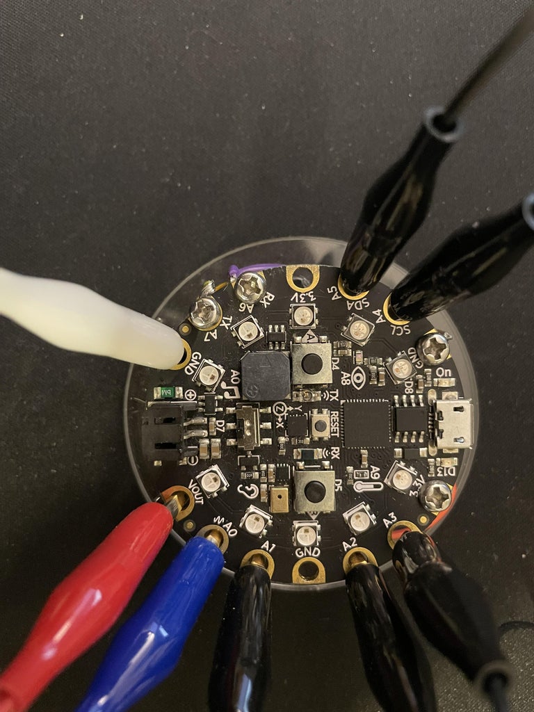


- Copy the setup from the breadboard image such that the 5 push buttons are connected together with resistors to get a stable input of electric current from the two extra cables (Orange & Red in image) - those will connect to power and ground while the 5 yellow cables will connect to our Circuit Playground Express board pins A1-A5.
- Connect each button cable to the correct pin, make sure that they are connected in the correct order (1 through 5 or 5 through 1) to pins A1-A5, and two more cables that will connect to GND and VOUT to create a button that controls an electric circuit.
- In the setup from the image: Yellow cables go to A1-A5 from right to left, Red cable to VOUT, Orange cable to GND.
- For the LED matrix: connect two of its cables to VOUT and GND according to their labels and DIN to A0.
- Make sure to keep the board cables neat and organized to prevent cables tangling and touching later on, if you wish to change any of the pins make sure you change the relevant parts in the code (can be tweaked in the main flow source code smart_doorbell.ino file).
Step 4: Make/Integromat Configuration


- Sign up to Make and sign in.
- Navigate to “Scenarios” section using the left menu and create a new Scenario
- Press the 3 dots on the bottom menu to “Import Blueprint” and upload this file.
- Edit and insert your devices’ names in the placeholders <> in that file.
- Click the “Webhooks” option on the screen and then the “Add” button to add a webhook, name it and then press save.
- Click “Copy address to clipboard” and paste it in the HTTP POST request (part of the setup of Node-Red).
- After finishing setup and deployment of your Arduino and Node-Red, the hook should receive an initial message that will define the type of structure for future requests’ data.
- Configure Apple IOS/Android modules, based on your phone, I present the IOS flow but the one for Android is the same:
- On the ‘Device’ section, press the ‘Add’ button,(example is attached as photo)
- Name your device and install the “integromat” App on your Apple device.
- Open the app and at the sign-in screen press “Use-code” and scan the QR given in the window (example image is attached)
- On the bottom menu click ‘Run once’, “Make” is now listening to incoming requests.
- On a new event trigger, a push notification (that contains a URL to a photo, or other link) will be sent to the device that was set up.
Note - unless you have a premium account on Make, there’s a need each time to press “Run Once” (which is practically Debug Mode).
Step 5: Node-red & MQTT Configuration


- Run Node-red locally (shown in link #1).
- Open the Node-red interface (when running Node-Red in the CLI, you’ll be able to see on which port it’s running should be 1880 by default).
- Open localhost:1880 on your browser.
- Add all nodes by using Import function (from the top right corner menu), importing this file.
Alternatively, you can do it manually by following these steps -
- Drag and add “mqtt in” node, double click it and fill as shown in attached image.
- Fill “Server” section in the "MQTT-IN" node as shown in attached image
- Drag and add HTTP-Request node.
- Double click the node and fill as shown in attached image.
- Fill in the URL section the URL that was received in the "Make Configuration" section, then press the "Deploy" button on the top right corner.
Note - Make sure there are no "red bubbles” around any of the nodes (indicating an error).
Step 6: Customizing and Final Tweaks
- For editing your guest list, edit the users map given in this part of the code.
- Make sure your internet connection credentials are inserted here.
- And that your IP is inserted properly here.

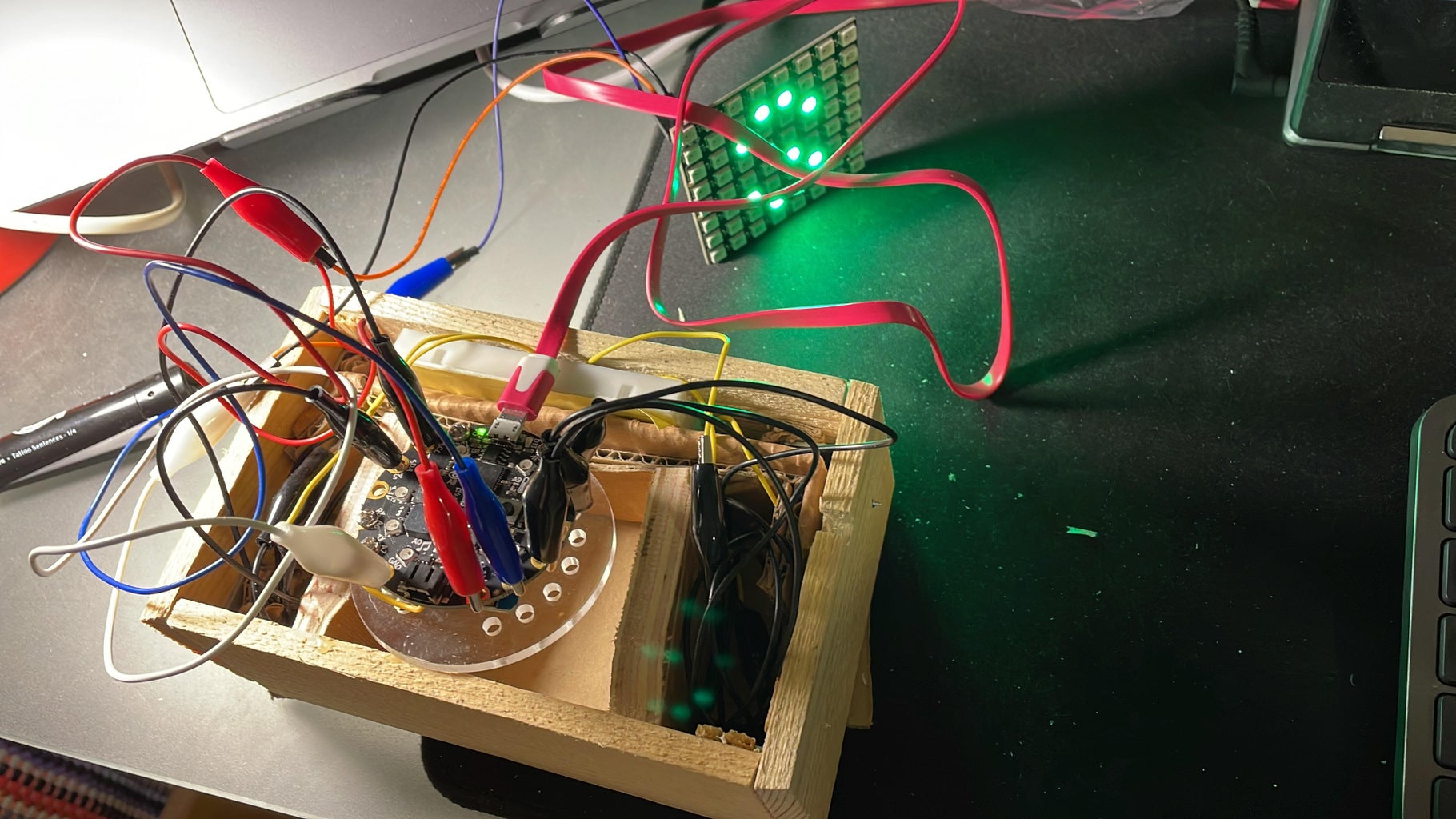
Step 7: Boxing


The boxing I used is an old torn up Monopoly board I found in the trash :D.
It is held together with some cardboard electrical tape, scrap wood, and double sided tape that was used to fix the LED matrix in place.
For me this is a temporary setup till my new soldering Iron arrives and I can wire everything up and put it in a cool 3D printed or a neat custom made wood box, will update on that so stay tuned!
Step 8: Last Thoughts
I must say I enjoyed this project very much, seems like a great structure for something that I can improve and further develop - add features and proper boxing.
I really liked how this project touched a bit of everything - from wiring switches and playing around with lights, sending requests via various libraries and technologies, it is really a great IoT project and a cool welcoming prop for my place, I hope you make your own and let me know how your friends like it, cheers!
Made by Tal Zuzut and Yoav Fried.


